I never thought this blog would attract a serious following, but it appears I've recently lost half my followers. That leaves me with one.
I sent my motor back to Sherline a couple weeks ago. They replaced the thermal switch. I hope that was the actual problem. They shipped it back, I won't get it for another week. In the meantime I decided to write code to do backlash compensation.
Backlash is the "play" in any mechanical system. Some have more, some have less. Some "cartesian robots" like milling machines claim "zero backlash" but I think they are really "near zero backlash". I don't know, maybe there are some seriously tight roller bearing systems that are truly zero backlash. I made a zero-backlash nut once. Unfortunately it was also "zero-movement" as it was much too hard to move. Epoxy makes a great zero-backlash zero-move nut.
My system has a familiar looking threaded rod (1/4-20) with a nut fixed to the table. As the rod turns, the nut and table moves up and down the rod. If you've threaded a nut on a rod before, it usually moves easily down the rod because there is space between the nut and rod. You can wiggle the nut a bit on the rod. Once you tighten it down to something, the slack is pulled out of it and one side of the "V" that makes the threads is pulled tightly together and it doesn't move.
When the rod is turned such that the nut moves away, the slack is all on the far side. When the rod is turned such that the nut moves closer, the slack is all on the near side. When switching directions the rod turns a bit without the nut moving while the slack "moves" from one side of the V to the other. This is backlash.
When working entirely manually, you can feel the backlash. I have a digital read-out unit on my mill. This DRO has electronic backlash compensation. I measure the backlash and key it in to the unit. It tracks the direction of movement and doesn't count the signals during backlash take-up. I've added the same concept to my host software and controller firmware. It's pretty sweet. My circles are nice and round now. A side benefit is that my code organization has improved. The Controller tends to get a little messy and I moved some code out into its own class.
The code to track and compensate was pretty easy but there were some unrelated bugs that got in the way. One problem in the host software involved code that deleted (merged) points on the path that were very close together. I failed to update the IN/OUT speed of the point so it matched. I was testing a path that ran the spindle full speed into a corner and it was overrunning and missing steps.
A while back I improved my stepping algorithm but it does appear there are limits to it. I step the "longest axis" of a line every loop and step the shorter axis (just 2 for simplicity) every N steps of the long axis. It's not really N, tho' for odd proportions. It may be 2-2-2-3-2-2-2-3, for example. Every other step for a few, then the third, then back to every other. Extreme cases may have the 2 axes in step for say, 100 steps then one axis skips a loop. At full speed this is enough to cause resonance of the stepper motor. (I'm not really sure it's resonance, but that's what I'm calling it.) This results in the stepper not moving at all, but sort of rattling in place. And losing tons of steps, of course. This explains one of my formerly unexplained cases of the spindle going off course. Going forward, cutting such extreme vectors will be done at a low enough speed that it won't be a problem.
I implement "uncoordinated moves" for rapids that avoid such extreme vectors and allow me to move at full speed. A coordinated move is when you move from point A to B in a straight line. The 2 or 3 moving axes are coordinated with each other. In an uncoordinated move, all axes (required to be moving) move at the same speed and each stops as soon as it reaches the desired position. An uncoordinated move is made up of "45 degree" lines and straight line segments. These vectors are no problem to handle at full speed.
My velocity planner sets the maximum speed through a point based on the angle. A zero degree angle is full speed. A 70 degree angle requires a full stop. I had to drop the 70 down to 45 as the rapid movements appeared to be losing steps. I think there's a lot of room to tune this, a slow speed cut probably does not need to stop, but it will probably be good enough for some time to come. I doubt I'll be terribly concerned with achieving maximum speed to reduce overall run time.
Monday, December 19, 2011
Saturday, November 26, 2011
Noise problems solved
Back in October I wrote about some phantom limit and e-stop triggers. The noise produced by the spindle motor is proportional to the speed. I wrote a simple program to monitor the limit and e-stop lines and turn on LEDs in response to state changes. With no debouncing on the lines, it was easy to see the effect of turning up the speed on the spindle on the noise.
The wiring for limit and e-stop is in two parts. Both use a standard 4-wire telephone line (the line that connects the phone to the wall jack). One part connects all the limit switches in series. The other part runs from the control panel circuit board to the stepper driver box. Two lines are the switches, the other 2 are the out and back of the stepper opto-circuit power.
All the other lines running from the control panel board to the buttons and LEDs are twisted pair bell wire. So I thought I'd try more of that. I ran the same stuff through all the limit switches. Since the 2 signal lines running to the stepper box were not "out and back" of the same signal, I thought the twisted pair might not solve the problem. So I picked up 50 feet of shielded microphone wire at Radio Shack and used it for the 2 signal lines.
Upon rerunning my noise test program I was able to run the spindle at full speed with no phantom limit or e-stop firing. Yay! I'm actually pretty happy with the Radio Shack wire. I'll probably redo the limit switches again with it.
The other problem I'm having is with thermal shutdown of the spindle motor. My original theory was that the thermal switch was faulty. The time to shutdown is proportional to speed. Under no load, 1500RPM leads to shutdown in about 30 minutes. At 2900RPM it's less than 20 minutes. I bypassed the thermal switch and connected it to a light bulb and battery so I could see when it was opening but not have it shut down. I ran the motor at 2900RPM past the point of the thermal switch opening. At the time of thermal shutdown the motor is warm to the touch but not uncomfortable. A few minutes past and it is noticeably warmer, I would say uncomfortably warm but I could still keep my hand on it.
I think that kills the theory of the bad thermal switch. I've talked to Sherline about it and they want me to send the whole motor and speed control assembly back to them. I'm not happy about that. It might be only a week or two delay, but it might cost close to $100, $100 I don't really feel like spending on the project right now.
It's possible the motor has always worked this way, I've just never run it long enough to suspect a problem, though I have experienced a couple thermal shutdowns in the past.
Sunday, November 13, 2011
Improved Stepping Algorithm
It would be good to re-read the post on the original approach to movement to get a good understanding of what's to follow.
This is a follow-up to yesterday's post about the resonance problems I was having. I concluded that I had 2 possible solutions to the problem, change the inter-step timing or adjust the vector so the "long" axis always steps when the other(s) step. I thought I'd do this in the host software by scaling up the values so we had common denominators or power factors or fractal deconversions or something. I thought that this might result in Really Large Numbers that would pose a problem for limited resources of the microcontroller. I briefly considered some sort of mathematical simplification of the vectors but thought I might lose accuracy. It seemed like I could produce something that would be good enough but it didn't seem like it was going to be easy.
I'll try to give a better idea of the problem. Referring to my earlier post and this illustration:

If we ignore the Z axis to simplify things, consider a vector of X:3 Y:5. This is actually a rise over run of 3 over 5. The inversion of what it sounds like, the lower number steps more frequently thus moves farther. First we take the lowest value and subtract it from all axes. This takes us from 3:5 to 0:2. The X axis is at zero, so we step it and reset it to 3. Then we subtract 2 from both leaving us with 1:0. Y is 0 so we step it. It continues like this:
X Y
3 5
0 2 X
1 0 Y
0 4 X
0 1 X
2 0 Y
0 3 X
0 0 XY
This can be illustrated like this, a time line of steps left to right. Red is X, blue is Y:

I went kite flying with my father and my son this afternoon. I was pondering the problem when an elegant solution presented itself. Rather than step an axis when the counter gets to zero, if I step all axes that are less than what was the smallest value prior to the subtraction, then instead of resetting the stepped axes to the original value, I add the original value back in. This produces the second line in the picture above. The X axis is the longest axis and it steps with every loop. It appears in this example that Y also steps at regular intervals, but another cycle through will show that Y has back-to-back steps from 5 to 6.
It was very easy to make this change to the code and it works very nicely. The problem vector is now perfectly smooth at full speed.
I ran a test path with a ball-point pen in the chuck traced on paper. The run took 4 minutes. Just as it finished the last part of the trace I got a phantom limit switch trigger. The spindle motor was not running. The fan in the controller box was, so that's a possible source. It's also possible my cell phone is a considerable source of noise.
I also forgot to mention a failure from last week. I was running a long test, about 30 minutes. Near the end the spindle motor shut down. It has a built-in thermal breaker. I wasn't cutting anything so no loss. I was running at 2000 RPM. I need to look at the brushes on the motor and see if they need replacing. If they look good I'll run a test at 1500 RPM and see how long the motor runs before a thermal shutdown.
I'm going to look into rewiring my limit switches with a shielded cable as well.
This is a follow-up to yesterday's post about the resonance problems I was having. I concluded that I had 2 possible solutions to the problem, change the inter-step timing or adjust the vector so the "long" axis always steps when the other(s) step. I thought I'd do this in the host software by scaling up the values so we had common denominators or power factors or fractal deconversions or something. I thought that this might result in Really Large Numbers that would pose a problem for limited resources of the microcontroller. I briefly considered some sort of mathematical simplification of the vectors but thought I might lose accuracy. It seemed like I could produce something that would be good enough but it didn't seem like it was going to be easy.
I'll try to give a better idea of the problem. Referring to my earlier post and this illustration:

If we ignore the Z axis to simplify things, consider a vector of X:3 Y:5. This is actually a rise over run of 3 over 5. The inversion of what it sounds like, the lower number steps more frequently thus moves farther. First we take the lowest value and subtract it from all axes. This takes us from 3:5 to 0:2. The X axis is at zero, so we step it and reset it to 3. Then we subtract 2 from both leaving us with 1:0. Y is 0 so we step it. It continues like this:
X Y
3 5
0 2 X
1 0 Y
0 4 X
0 1 X
2 0 Y
0 3 X
0 0 XY
This can be illustrated like this, a time line of steps left to right. Red is X, blue is Y:

The top line is the original implementation. Given constant speed, the time between each number is the same. So the time between X steps varies as it does for Y. For low speeds or ratios where the variations are frequent enough, this doesn't seem to be a problem. The vector that was failing had a ratio of greater than 1:22. At full speed this produced resonance. I can't really say why, I just seem to have an intuitive understanding of it. It seems a good solution is to adjust the timing between the events, that way both axes could have regular timing. I gave it shot, it was fairly easy to code. But it didn't work. I'm working in integers and there isn't enough resolution in the timing to make this work. That's the way it seems, I'm not yet positive it CAN'T be done this way.
I went kite flying with my father and my son this afternoon. I was pondering the problem when an elegant solution presented itself. Rather than step an axis when the counter gets to zero, if I step all axes that are less than what was the smallest value prior to the subtraction, then instead of resetting the stepped axes to the original value, I add the original value back in. This produces the second line in the picture above. The X axis is the longest axis and it steps with every loop. It appears in this example that Y also steps at regular intervals, but another cycle through will show that Y has back-to-back steps from 5 to 6.
It was very easy to make this change to the code and it works very nicely. The problem vector is now perfectly smooth at full speed.
I ran a test path with a ball-point pen in the chuck traced on paper. The run took 4 minutes. Just as it finished the last part of the trace I got a phantom limit switch trigger. The spindle motor was not running. The fan in the controller box was, so that's a possible source. It's also possible my cell phone is a considerable source of noise.
I also forgot to mention a failure from last week. I was running a long test, about 30 minutes. Near the end the spindle motor shut down. It has a built-in thermal breaker. I wasn't cutting anything so no loss. I was running at 2000 RPM. I need to look at the brushes on the motor and see if they need replacing. If they look good I'll run a test at 1500 RPM and see how long the motor runs before a thermal shutdown.
I'm going to look into rewiring my limit switches with a shielded cable as well.
Saturday, November 12, 2011
Binary Protocol Deployed
A month ago I thought I was close to routing my first circuit board. I had some problems with the running of the toolpath. I thought the general problem was noise and I may have been right, I still have more data to collect on that. I found that the spindle motor produces enough noise above 2000 RPM to interfere with things, particularly the E-stop. I was running at full speed, 2500+. Staying under 2000 helped a lot.
Suspecting bad communications, I rewrote the serial protocol. The packet design, bit shifting and checksum all went well. Getting the 2 "nodes" to carry on a dialog proved to be quite a challenge. Clear exchanges were no problem, correcting errors was. A low error rate was easy to deal with. My protocol does not send an Ack, just a Nak. I decided to leave the Ack to the business layer. Higher error rates with back-to-back errors turned out to be difficult to deal with.
Imagine I'm in the back seat giving you driving directions. I say "turn left", you turn left. If you don't understand me you say "say again". Then I repeat what I said. But if I say "turn left", you say "say again" but I don't understand that, I say "say again". The last thing you said was "say again" so you say it again. the last thing I said was "say again" and we are in an active lock.
Another scenario results in you hearing "turn left" twice and we go down the wrong street. I managed to fix the first scenario but not the second. I set up 2 Java threads talking to each other with random error injection. A few errors in a thousand was no problem. 5% errors led to duplicate messages. Around 3% errors the code could handle. I suspect the real error rate will be much, much lower so it should be good enough.
I dropped the new binary protocol into the firmware and ran my circuit board tool path. In addition to the noise problems I had some "transport" problems, meaning the machine didn't move the prescribed distance. Some of the moves seemed rough and there was some stalling too (resonance?). I don't mean the motors weren't strong enough, there's like no resistance here. This is a problem with pulse timing. The motors need to get pulses with timing that is appropriate for the current speed of the motor. I've written about that before.
The question is why is this coming up now after all the programmed paths I've run? The toolpaths generated by the various software tools I've been using that convert SVG and other sources to Gcode have been producing various conditions that reveal flaws in my code. The paths I've been generating from Java are relatively simple. This is the vector that was running rough at best, stalling at worst:
X:1203 Y:260741 Z:0
Since Z is zero, we're not moving vertically. I'm using a Bresenham algorithm (I think) to move the axes in some ratio. Above, the axes move in something like a ratio of 1203:260741. I say "something like" because it's actually the X axis that is longer. I've written about this before, too. I subtract 1203 from both values, X is then zero so I step it and reset. I continue this until the Y value is zero and I step it. If the machine is moving at a constant velocity, the time between pulses is fixed. Each axis that moves should step at a regular interval. With my implementation, I subtract the smallest value from all until one or more is zero. That's X most of the time until Y gets down to 893. Then I subtract 893 from both. Y is now zero but X is 310 so I step Y. Then I subtract 310 from both and step X again. So X and Y are not stepping at the same time. I don't think this is a problem, the problem is that the time between steps is fixed which means we waited twice as long as we were supposed to between X steps while we were stepping Y. At least that's my theory. I changed the Y value to 260744 which is evenly divisible by 1203. This resulted in much smoother motion and no stalling.
At some point early in the process (almost a year ago) I ran across this post by Thomas. He touches on the Bresenham algorithm and some more advanced acceleration algorithms. In the case he gives, a ratio of 3:2 is smooth enough. A ratio of 3:8 should result in the same problem I have above. Thomas talks some serious stuff about stepper motor modeling. I'm still feeling positive that I can keep things pretty simple and still get good performance.
I'm not quite sure what approach to take to solve this. I could tweak things in the host software so that the axes ratios are such that the longest axis steps every loop. I might lose some accuracy, though. Another idea is to use the axes ratios to drive the timing between steps. I can't really think of a coherent way to describe what I'm thinking off. I'll try to work it out on paper and post it later.
Saturday, October 29, 2011
Halloween Costume
A couple posts back I wrote that I was working on my halloween costume. Here's the result:

Again, here's the inspiration:


Again, here's the inspiration:
Thursday, October 20, 2011
Serial Protocol Testing
I love metrics. Real data that demonstrates the truth (or falsity) of a claim. Try to convince me of something using "anecdotal evidence" and I'll call you out for it.
My new robust serial communications protocol is coming along. In my day job I write "high-level" code working with models of business concepts and logic. It's been a long time since I've gotten down and dirty and worked directly with bits and bytes.
I hinted in my last post that I was going to use a MIDI-like protocol. The first byte has the left-most (MSB) bit raised. This marks the start of the frame/packet. All other bytes in the packet have the MSB cleared. This means each byte holds a "value" in 7 bits. The other 7 bits of the first byte carry the command. I clear the high bit to extract the command, then the next 5 bytes have to be bit-shifted into a 32-bit variable.
All this is pretty easy, really, I just haven't done much of it in Java. I got tripped up for a while because Java datatypes are all signed. Funny things happen when you shift bits left and right in signed datatypes. I learned about two's complement in college but never used it after that. The solution was to work with integers instead of bytes and just waste the extra bytes.
The last 2 bytes in the packet hold a checksum. I implemented a "Fletcher 14" checksum algorithm. I made that up. There's a 16 and 32 bit Fletcher checksum. Since all my data bytes have 7 bits, I can't do a 16 bit Fletcher without spreading it out over 3 bytes and having to do more fancy bit shifting. Probably wouldn't have been a big deal.
So back to the metrics thing. I've never written a checksum before, so I need to know if it works. I wrote a test program to randomly inject errors into the packet. I flipped 1 to 3 bits and swapped bytes in the packet. I ran 1.2 billion iterations with 1/4 billion errors. The checksum missed 47K errors. That's 1 in 5000 errors missed. That's pretty good for a checksum. The computational cost if this algorithm is low so I'm pretty happy with this outcome.
Then I wrote the code to handle the serial transmission of the packets for the Java client (the Arduino code is in C). It's much easier to debug in Java, so I connected 2 Java serial drivers together with a "ManglingInputStream" between them. This randomly injects dropped bytes and flipped bits. This demonstrated that error handling was sound. It would have been pretty hard to write it for the Arduino and throw it into the shop and wait for errors to happen. I'll collect error reports later so I know what the real-world error rate of the system is.
Wednesday, October 12, 2011
Robust Communications
I experienced a bit of a setback yesterday. I set up to make a test run of the smaller PCB design cut from a block of plaster. I experienced 4 failed runs. 2 failures were due to phantom triggering of the limit switch or E-stop. The other 2 failures involved the machine taking the wrong path.
Electrical noise is a common problem in systems like this. Motors are a great source of "static" to confuse the logic circuitry. This often leads to misreads of switch inputs. The wires I'm using for the limit switch and E-stop are 2- and 4-conductor telephone wires. They aren't shielded. Also, when I am running "programs" (toolpaths from the computer) I power the Arduino from my laptop which is running off battery. I don't think that constitutes a quality grounding of the system. I bought a power supply for the Arduino a little while ago. I'm going to start using it, it might help with this situation. The firmware "debounces" the switches by requiring a state change to last at least 10ms. I can increase this until I can get some better shielding in place. Can't go too high or the machine will pop the switches off and I'll have to fire up the hot glue gun again.
Twice the spindle clearly went in the wrong direction. Off the toolpath that is. The first time it simply bore into the plaster block. Good thing it was soft plaster or I would have lost my $20 0.015" end mill. The other time it ran off the back boundary of the board then came back and went up instead of down. I don't have a real good explanation for this. The only thing I can imagine is data communication failure. I'm using a simple character-based packet for sending a command and a parameter. If a character gets lost now and then this could certainly send things south. With a high baud rate plus all the interrupt handling I'm doing it might not be unexpected to lose one character every five or ten minutes. I have no idea, really, I'm just guessing.
So it's time to make a proper binary communication layer with a checksum. I've done some work with MIDI-like protocols so I'll probably stick with that. MIDI is a single command byte with a 14-bit data portion. The command bit has the last bit raised to mark the start of the packet. All other bytes have the last bit low. Bit shifting will be required to put it all back into 8-bit bytes. I need 32 bits in the data so that's 5 bytes with 3 left over bits. Then I'll add a checksum. I've never written a proper checksum. I'll probably use a simple XOR (exclusive or) checksum. I'm not sure how many bits is good for that. I'll use one or two bytes for the checksum. That's 7 or 8 bytes per packet. That's a lot less than the average character packet for sure.
I'm off to prototype it in Java. I'll start with Java talking to itself. Once that works I'll have half the code I need and then I'll port the solution to the Arduino.
Monday, October 3, 2011
Copper Test Path
I got the micro end mill for the isolation routing. I ran a test on the plaster and it looked pretty good. Well as good as fine plaster routing can look, I guess.
The copper PCB board came in, too. I'm pretty sure the 12" x 12" board represents a life-time supply. I made a sacrificial tooling plate from 3/4" MDF. I faced the top with the fly cutter. I swept the top surface with my dial test indicator to check it for level. It was quite flat but bumpy. The next step was to mount a test piece of the PCB. Flat. That's the hard part, actually.
I don't have a decent clamping mechanism for holding down the PCB. I read how some others have done it. First I drilled holes around the perimeter and screwed it in place with the screw heads overlapping the edge of the PCB. Surprisingly that didn't work. I drilled a couple holes in the board and put in more screws. Still no go. It was fairly easy to push down the corners and see the board move.
Next I tried double-sided cellophane tape. That didn't work. The PCB board appears to have a curve in it, probably just one axis. It's tough stuff, too. It appears it's going to need a thorough, strong clamping or other hold-down method. I read about one person's approach where he uses an aluminum tooling plate and glues the PCB down with CA/Krazy Glue/Super Glue, Cyanoacrylate. Then he uses acetone to soften the CA and remove it from the plate. I'm not real clear how he did the drilling. Maybe he drilled into the aluminum, I don't know.
I haven't had much luck with CA myself, at least not the hardware store variety. Maybe the industrial kind is better, but I never find it "bonds instantly" with much strength. I can't get anything to hold together with it, actually. I went to Lowe's (home center) and looked over the adhesives. I figured the tape didn't work so I didn't want to buy something that wouldn't be otherwise useable. I suppose I could have tried some 5-minute epoxy I already had... Anyway, I decided to give Gorilla Glue a try. Not the "super" variety, just regular GG.
I applied the GG to the MDF tooling plate, sprayed it lightly with water and put the PCB on. I clamped it really well and left it over night. Next day, I swept the surface and found it was much flatter but still had about 5 mils variation. I was pretty bummed at this point. I really didn't expect to have such a problem holding it flat. I decided to go ahead with a test cut anyway.
I set the system up to cut at "zero" depth. It's tough to set the Z height just right, so this was playing is safe. It did cut lightly into the copper on one half and through the copper on the other. I lowered it 2 mils and ran it again. This resulted in a complete cut over the whole path which is really a pretty small area. Here's the result:

The isolation is complete, the edges are clean. I had done a test cut on the red resin material. I don't have a photo because the cut was so clean you really can't see where the lines are. The cuts I did with the cheap conical bit are white on the red because the edges are actually fuzzy.
The Gorilla Glue is pretty good stuff. I thought GG was at least partially CA but it may be that the standard formula is polyurethane only. I put so much on it was clear I wasn't going to soften it with anything. I tried some Goof Off anyway (Xylene formula). Finally I just ripped it off with a chisel. Quite a lot of the MDF came off with the board. This was not going to be a solution for the actual production.
Then I glued a piece of PCB to a piece of plexiglass using much less glue. I clamped it real well and waited overnight again. The 6 or so small drops spread out to cover almost the whole surface. To my surprise a little easy flexing of the plexiglass separated the PCB. There was no glue on the plexi. I tried some nail polish remover (with a large acetone component) to remove the GG from the PCB. I don't think that route is going anywhere.
The glue is on the component side, of course. It makes a nice shiny surface if the coverage is complete. It might not be a problem at all to leave it on there. Maybe there's something I don't know that will lead to trouble. We'll see. Maybe I'll find someone who knows a little more about it.
After taking the above picture I drilled a 1/32" hole in the small pad in the middle and soldered a scrap lead to it. The solder went on nice, so all the questions about isolation width, pad area around drill holes and solderability have all been answered favorably.
Monday, September 19, 2011
Oiling Apparatus
In my last post I ended stating that I should probably do another test on a copper board to test my depth of cut (so I know how wide my isolation paths will be). I did that test. I either broke the tip or severely dulled it because I can't get any clean lines with it now. This is a 5 dollar Dremel conical cutting bit (HSS). I figured it was worth a try. I decided to order a proper 0.015" end mill in carbide. I also ordered a 1/6" bit. I've got an 1/8" and 3/8" so that gives me a good amount of flexibility.
I also ordered all the electronic components for the 2 PCB boards. While I'm waiting for all the stuff to come in, I thought I'd take care of a maintenance problem. The Y lead screw and ways are super easy to oil. The X is very difficult. It's all underneath the table so hard to see, plus gravity pulls the oil down so you have to get it above the part to be oiled. So I made a simple oiling tool. I picked up a cheap "rear view extension" mirror for a car and liberated it from the mounting system:


I also ordered all the electronic components for the 2 PCB boards. While I'm waiting for all the stuff to come in, I thought I'd take care of a maintenance problem. The Y lead screw and ways are super easy to oil. The X is very difficult. It's all underneath the table so hard to see, plus gravity pulls the oil down so you have to get it above the part to be oiled. So I made a simple oiling tool. I picked up a cheap "rear view extension" mirror for a car and liberated it from the mounting system:

I also got some tubing with 1/6" ID:

This is a "variety pack" - it's got 2 items in it both with 1/16" ID but different ODs. Anyway. I made a "wand" out of 14ga house wire. I put some heat-shrink tube around the end to hold the tube to the wand. Another piece of heat-shrink at the other end of the tube made for a nice adaptor for the oil can. Here's a pic of it all on the workbench:

I'm a capable photographer, but I'm finding many of my shop pics are looking rather crappy. Like many, this has some focus problems. You can see the mirror under the X/Y table showing the X lead screw and ways. I'm holding the wand in the lower left. That's the oil can that says "oil" on it. I hold the oil in one hand, wand in the other, then gain a boatload of appreciation for my dental hygienist that can do fine manipulations in a mirror. I dumped way too much oil on the system the first time, but better than too little.
I also started work on my halloween costume. Here's the goal:
Wednesday, September 7, 2011
Scaling Problem Fixed
In my last post I said my circuit board path test resulted in an engraving that was 80% of the size it was supposed to be. That number didn't ring any bells at the time. Later that evening I was brushing my teeth and thought, "What's 72/90?" I grabbed my phone (my Sharp scientific calculator died years ago) and ran the numbers. The answer? 0.8!
So where did I get 72 and 90? I remembered reading somewhere recently that Inkscape (the SVG drawing program I'm processing the design with) works in "pixels" as its base unit of length. "Pixel" is short for "picture element". It's the smallest dot the computer can make on the screen. Which means it's pretty arbitrary. The actual length of a line 150 pixels long depends on the size of the monitor and the resolution the display is set to. Anyway, what I read said Inkscape assumes 90 pixels per inch.
Years ago when I worked in graphic design, monitors were smaller and video displays were lower resolution. Back then, 72dpi, dots per inch or really pixels per inch was the convention. So there're the 2 numbers that popped in my head. I wondered if there was some error in the software. Obviously not mine since I did a Java-only path that measures out correctly.
The GCode plug-in I'm using in Inkscape is written in Python which I know a little about. I couldn't find any factors for scaling hard-coded into the exporter. The plug-in asks Inkscape for the conversion factor. I set my document to inches and sure enough it returns 90 like the documentation said it would. I simply hard-coded 72 as the scale factor, exported the GCode again and my host software reported the proper extents.
I ran the program and got this:

It's pretty hard to measure such a thing as this. Using my dial caliper and magnifying glass I took a couple of rough measurements. The PCB design software says the traces are "thin" or 0.016". I expanded the path to use as much room as possible (two adjacent circles nicely come together at a tangent) and the traces seem to be closer to 20 mils. The small pads for the DB-25 I measured somewhere around 60 mils. According to Inkscape the pads are... 60 mils. That's pretty cool.
I drilled a hole with my 1/32" drill bit, the smallest I have. There isn't much room around it. I definitely need a smaller bit. I might reshape the pads, make them rectangles, to give me more room to solder.
So it looks promising. My goal was to determine if I could isolate the paths and still leave enough copper to solder to and looks clear that will work. Really I should do another test on some real copper to check the isolation using the depth-of-cut I used on this test.
Ok, I just ran downstairs and did a test on a scrap perf board. The depth I used on the red piece was 10 mils. That didn't cut all the way through. I dropped down 5 more and it cut clean. According to a quick geometry check in QCad, the difference in width from a 10 mil deep cut to a 15 mil deep cut is 3.3 mils. I don't think that's significant, so I'm still feeling positive.
On more thing. You might notice the pad circles are not real, well, circular. I'm sure this is the effect of the backlash I'm totally ignoring at this point. I'll address that another day.
Monday, September 5, 2011
Circuit Board Design
I spent a fair amount of time working in Fritzing on the circuit board designs. One is for the box that holds the manual controls (the control panel), the other goes in the box with the stepper driver control board. I'm exporting the PCB design as an "etchable" SVG. Here is a first draft of the control panel:


All in all, I'm not happy with the GCode generating tools. I've got 2 plug-ins for Inkscape. One is very minimal, the other is quite complex and neither has much in the way of documentation. So I may end up writing my own SVG reader to generate paths in the Java model.

Along the top is the DB-25 connector. The holes are a little over 0.100" apart but as you can see I have to get a trace in between each one. The traces in this illustration are 0.016" wide. I'm using a conical cutting bit and I don't know how deep I'll have to cut to isolate. Once I figure that out I'll be able to figure out how wide the cutting path will be. My concern is that I'll be cutting a path that's wider than the space between the traces and the traces will be too thin. Worse is that the pads will be too thin and I'll drill it all away.
The etchable design then goes through some manipulation to expand the elements to account for the width of the cutting bit. Then I export to GCode using a plug-in in Inkscape.
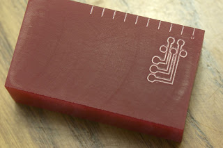
I mixed up a pot of plaster of paris and made a brick to do some practice cuts on. I don't have any pictures of it because it's not very impressive. I made up a test design that incorporates both the size and spacing of the DB-25 pads and traces plus standard 0.100" pads. I squared up a piece of cured polyurethane resin and cut the test path:

I arranged the path to make the pads and traces as large as possible, i.e., the path around the pads is more or less coincidental with the path along the traces between the pads. While is looks like it will isolate ok, it seems quite tight. The smallest drill bit I have is 1/32" which will probably create a hole around 0.050". I think that will wipe out the small holes on the DB-25 connector. Not good.
The three larger pads at the lower left are standard-size holes on 0.100" spacing. Or are they? I held up a standard header pin thingy against the three holes and they don't add up. ("Cat don't want to eat mice, wants dog to massacre him...") I wrote a quick program entirely in Java to cut the lines across the top at 0.100" intervals and they line up just right with the header. So something is wrong with my tool chain.
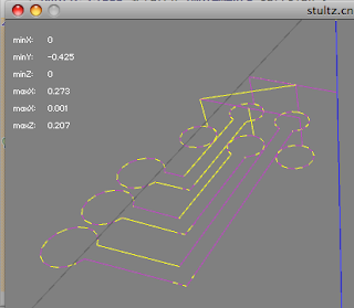
The good news it that the path is too small, so when it's fixed the pads and traces will hopefully be big enough to accommodate the 1/32" drill. I added a feature to the host software to calculate the extents of the mill movement, the minimum and maximum positions on each axis. Here's a screenshot of the SVG design. The page is sized to the path.

As you can see, the path area is 0.34 by 0.53. Here's the host software with the extents displayed:

The min X and Y are 0, the max are 0.273 by -0.425. It's 80% of actual size. I'll have a look at the plug-in for generating the GCode. Maybe there's some unit conversion error.
Sunday, August 14, 2011
Acceleration Calibration and GCode Parser
I spent some time tweaking the firmware and host software recently. I fixed a few bugs on both mostly related to automated program running (the main task of the system, "running the GCode"). It seemed the firmware was not moving the spindle as far as it was supposed to. It seemed to move it different distances depending on the position of the throttle (feed speed override).
The class modeling the stepper driver has a vector that it is moving along. One component is the target speed, another is the number of steps to take. When the spindle is supposed to come to a complete stop, the period (time between steps) will be "MAX_PERIOD". The function that tests whether the spindle is moving asks whether the number of steps to take has been reduced to zero, or the period has reached MAX_PERIOD. When running at full speed it was going as far as it needed to. But when I slowed it down it didn't go far enough. That's because the deceleration rate is the same regardless of top speed and it was in fact stopping "faster" (over a shorter distance).
It probably wouldn't make sense to evaluate the period equaling MAX_PERIOD to see if the spindle should stop when the system were only to run in automatic (GCode) mode. But my system has several modes including a "continuous manual" mode. The firmware doesn't know when I'm going to release the button nor how long it takes to come to a complete stop. So I set the vector to a million steps and it stops when the speed slows to MAX_PERIOD. So I just told the host software to target the speed of MAX_PERIOD - 1 so now it runs out of steps before hitting the stop speed.
I also calibrated the FAD (full acceleration distance) by writing a graphing routine that mimics the firmware acceleration and counts the number of steps and microseconds it takes to accelerate. I dropped the 2 middle split points in the ramp formula since I decided to go with as straight a ramp as possible. Changing the period by large amounts (25 microseconds per step) at low speed and interpolating the change to 1 microsecond at high speed produces a pretty straight ramp. Up near high speed it is problematic. I'm using integer math to save clock cycles but this creates a bit of a problem at high speed:

Above is the integer-math solution. The ramp is great right close to the top then it gets a little screwy. At some point I start taking 1 microsecond off the period every loop. This creates an exponential curve. If I switch to floating point math I get this ramp:

The whole thing is nice and straight. I don't want the cost of floating point math, at least not now. I may experiment with it later, but it probably doesn't matter that much. I've settled on a minimum period of 300 microseconds between steps. If I go down to 250 or 200, that sharp upward curve causes the steppers to rattle. It doesn't rotate, it just snaps back and forth between 2 positions. 300ms is fast enough. I don't want to wear out my machine and it's WAYYYY faster than cranking by hand.
Now that I've calibrated the FAD I can actually go back and plug that in to the firmware to make a better solution to the stopping bug above. When the button is released, I could set the number of steps = FAD and remaining steps would be the only thing to evaluate.
I wrote a simple GCode parser. All it does is take the X, Y, and Z move commands and build the path in my Java object model. Running a few paths generated by external programs revealed some weaknesses in the host software. I patched a few things up and dropped one of the 3 acceleration scenarios. In some cases the distance between 2 points and the change in speed is such that the spindle can get to full speed before immediately slowing back down to the end speed. This distance is very short, the FAD is only 600 steps (0.075 inches). I decided it might be smoother to leave this out and it will certainly reduce the number of vectors to send to the controller. A lot of this sort of stuff I'll continue to tune after I start running programs.
I'm going to start using the Fritzing software to design my circuit boards. Eagle is pretty powerful, I've read, but Fritzing has a pretty low barrier to entry and I like its association with the other technologies I'm using. Here is a very simple test PCB design in Fritzing:

Fritzing doesn't export GCode but it does export Gerber, PDF, SVG and others. I messed with Gerber and a program called Visolate but had some trouble with it. I then exported as "etchable SVG". I opened the resulting file in Inkscape, did some path operations and came up with this:

I found a simple plugin to export selected paths as GCode. I ran the file in my host software to produce this. It's not pretty, but holy cow, it's a tool path for cutting circuit boards! Sweet:

Thursday, August 11, 2011
Found It!
A couple of months ago I got new tires for one of my cars. I was heading out with the family on a road trip. I wanted to track the wear on the tires so I grabbed my metal machinist's ruler. Other than my calipers (and a four-foot drywall t-square), it's the only measuring device I have that can measure to "the bottom" or an inside edge of something. That is, the end of the ruler is where the measuring starts.
I recorded the tread depth and placed the ruler on the end table by the front door. As I said we were on our way out.
I'm married with children. I love my wife, I really do. There's a song by Sixx A.M. with the line, "and I'm losing my mind 'cause she hides all my shit". I always think of her when I hear that. She doesn't hide my things per se, she just moves them. For some reason she just doesn't like where I leave things.
When I set the ruler on the end table I knew I had better put it away when I got back or she would find it and move it. Sure enough I delayed and it was moved. I saw it later on the kitchen table. (We don't have a kitchen table, but that's what she calls it, don't get me started on that.) I thought, "hey I better put that away or it will disappear." Still no action from lazy me. I didn't do anything and it disappeared.
Neither my wife nor kids had seen it or remembered putting it anywhere. For months I cursed her name (whatever that means) as I used a six-sided architect's scale to try to measure "from the bottom" of stuff. I thought about buying a new one but I couldn't shake off the lazy.
Yesterday I was looking for the blades for the power knife. I didn't find them in the first two places I looked. My wife thought they should be in the utensil drawer as did I so I really went to town digging for them. I lifted the silverware tray out of the drawer and much to my surprise, there was my metal ruler UNDER the silverware tray in the utensil drawer.
So let that be a lesson to you, married men. Don't leave your toys out if you want to keep playing with them.
Wednesday, July 27, 2011
Two Thousand Dollar Spirograph
I may be dating myself with the title of this post. Back when I was a kid, there was a toy called Spirograph. It was an art toy. There were a series of geared rings, wheels, and multi-colored pens. You arranged the parts various ways and put a pen through a hole in a wheel. You used the pen to turn the wheel inside or outside a ring and it made a repetitive design like this:


This is a pretty lousy picture, I know. It looks like the foreground is out of focus. Maybe it is, but the lines are very faint as the surface wasn't perfectly flat. There's a circle in there somewhere. Maybe you can see it in the full size. Here's the code:
m.setHeading(0.0f);
for (int i = 0; i < 8; i++) {
for (int j = 0; j < 4; j++) {
m.forward(0.25f);
m.right(90.0f);
}
m.right(45.0f);
}
m.down(0.25f); // todo: Z is inverted
m.setHeading(0.0f);
m.forward(0.125f);
m.up(0.25f);
m.setHeading(90.0f);
int steps = 16;
float step = (float) (2 * 0.125 * Math.PI) / steps;
float turn = 360 / (float) steps;
for (int i = 0; i < steps; i++) {
m.forward(step);
m.right(turn);
}
m.moveTo(0, 0, 0);
The circle is off center. Can you spot the error in the code?
All in all I'm pretty happy with it. I've got quite a bit of tuning of various parameters to do. My steppers are 200 turns per revolution running in 1/2 step mode, so 400 turns per revolution. The screws are 20 turns per inch, so the steppers make 8000 steps per inch. I ran another simple path to move the table one inch and my DRO says it's a bit short. I ran it at full speed and it went farther than at half speed. I believe this indicates the deceleration phase was too short and the machine (the motor most likely, I think) was overrunning. I tweaked the FAD and got the same distance from full and half speed runs. Unfortunately the distance was not 1.000 inches. I compensated for backlash but it was still short. Not sure what's going on there.
I ran my first automated CNC operation yesterday. I wrote a little program to make a simple pattern that reminded my of Spirograph. I decided to run it in the air first. The steps-per-inch setting way wrong and the pattern was too large. The mill table hit a limit switch. I fixed that up, put a pencil in my drill chuck and taped a piece of paper to the mill table. The first attempt failed when the mill pushed the pencil into the table instead of lifting it up. My Z axis direction is inverted. I got a chance to test the E-stop button! Both safety measures working!
The run was excruciatingly slow as my "Full Acceleration Distance" (see Acceleration post) was way too high. I patched up the program and ran it again. It ran much faster and completed without incident:

m.setHeading(0.0f);
for (int i = 0; i < 8; i++) {
for (int j = 0; j < 4; j++) {
m.forward(0.25f);
m.right(90.0f);
}
m.right(45.0f);
}
m.down(0.25f); // todo: Z is inverted
m.setHeading(0.0f);
m.forward(0.125f);
m.up(0.25f);
m.setHeading(90.0f);
int steps = 16;
float step = (float) (2 * 0.125 * Math.PI) / steps;
float turn = 360 / (float) steps;
for (int i = 0; i < steps; i++) {
m.forward(step);
m.right(turn);
}
m.moveTo(0, 0, 0);
The circle is off center. Can you spot the error in the code?
All in all I'm pretty happy with it. I've got quite a bit of tuning of various parameters to do. My steppers are 200 turns per revolution running in 1/2 step mode, so 400 turns per revolution. The screws are 20 turns per inch, so the steppers make 8000 steps per inch. I ran another simple path to move the table one inch and my DRO says it's a bit short. I ran it at full speed and it went farther than at half speed. I believe this indicates the deceleration phase was too short and the machine (the motor most likely, I think) was overrunning. I tweaked the FAD and got the same distance from full and half speed runs. Unfortunately the distance was not 1.000 inches. I compensated for backlash but it was still short. Not sure what's going on there.
Saturday, July 23, 2011
Finished!
Now that I've written the title for this post, I have to admit that a project like this is never finished. I mounted and wired the limit switches, so all the minimal requirements have been met. I just hot-glued the switches to the machine.
I set about testing the switches. I wrote earlier about the control process in the firmware. After opening the limit switch circuit (they are wired in series) the steppers shut down. Obviously you need to then back the machine out of the corner you're in. So pressing the throttle button switches to "escape mode" and the limit switches are ignored. I ran the spindle into the upper Z axis switch and it stopped as designed. I entered escape mode to pull away from the switch. Then I moved the table to the front edge to test that switch. It's possible I forgot to exit escape mode because the table plowed through the switch popping it off and then ran into the hard stop. This caused the screw holding the coupler to the end of the lead screw to come loose. The stepper just spun in place without moving the table. I had to remove the stepper motor and re-tighten the screw. After restarting I completed testing all 6 switches.
So now I have all the hardware in place, but it's time to start making it better. What's really cool about a project like this is that I can now use the machine to make the machine better. First I need to write a G-Code interpreter to build tool paths in my Java object format. This will allow me to use a plethora of other tools to generate tool paths. I have some tools for designing circuit boards and generating milling paths. It looks like I'll be back on the computer for a while now. I'll be designing 2 PCB boards, one for inside the control box, the other for the control panel.
Sunday, July 10, 2011
Limit Switches, Limited Progress, Reduced Backlash
Progress has been slow. After school got out we took a vacation, then we had a holiday weekend. Weather has been great, lots of barbecues. I spent most of the day yesterday doing some nature photography. Just before vacation I realized I needed to order some parts and I didn't want to do that until we got back.
I have the Sherline DRO that has special collars for mounting the encoder wheels. The X and Y collars mount on the back shaft of the steppers nicely. The Z axis collar is very different. I needed to order another one like the X/Y collar design. Sherline makes a device for the Z axis that allows tightening the saddle nut lock bar to reduce the backlash. I decided to get that, too. The kit includes a new saddle nut and lock bar which I really don't need. I'm not going to use it, just stick it in a drawer until my current Z axis wears out. I also thought it would be good to use Dremel bits with the mill for engraving so I got a 1/8" collet.
After getting the DRO handwheels remounted I was able to check the backlash. The DRO has electronic backlash compensation, basically not counting a certain number of clicks when the direction is changed. Prior to mounting the steppers, the backlash on my mill was 3-5 mils. After mounting the steppers and the Z-axis saddle nut kit, my backlash is now 1-2 mils. That's quite an improvement. The stepper mounts are so solid, there's no play at that end, so that just leaves the backlash nuts to tighten up.
I've been thinking about how I'm going to deal with backlash. I may write about that some other time. For now, I'm going to ignore it altogether since it's so low. I want to move on to getting productive with the system.
I'm supposed to be working on the limit switches now. It's not obvious how to mount the switches, certainly not in a way that looks good and is out of the way.
I did do a functional test, though. I measured the movement of the switch. The switch would move some amount I can't recall before getting to the "click" point, then another distance before bottoming out. I made a quick estimation of how many steps the motor would take to move from the click point to the bottom out point. The limit switch signal is polled in the main loop of the firmware so there would be a delay from the change of the switch to the time the steppers would be told to stop. I don't remember the numbers but it seemed likely the steppers would stop before bottoming out on the switch.
I used my favorite prototyping tool, the hot glue gun, to mount a switch and a stop block to the table. Then I ran the table into it at full speed. The steppers came to a stop even before the switch got to the click point. Sweet. The hot glue held well. I messed up the controls a few times and ran it further into the switch and the piece of plastic I used as a stop block would pop off.
My first automated project will be 2 circuit boards for the stepper box and control panel. I happened to be at the hardware store that sold Dremel bits. They didn't have a certain engraving point I wanted but I did pick up a cutting bit that looks to have like a 45 degree point on it. I mounted it in the mill and mounted a scrap PCB on the table. I brought the spindle down and nearly or lightly ran it into the hard stop. This was my first operation with the "power feed" or manual control. So, uh, yeah, I need limit switches on this thing.
I made a very light cut, maybe 6-8 mils deep. I cut a trace in two with a pretty thin line. It looks like it will do the job of cutting my PCBs just fine.
Sunday, June 12, 2011
It's Alive!
I installed the motor mounts and mounted the steppers this weekend. I'm used to the various phases, stages, sub-projects, etc. taking pretty long, so this seemed like it went really fast. The instructions were good but could have been better. Some of the illustrations were lacking detail. I had to put on the "preload nut" at one point. This nut is not symmetrical yet the instructions didn't mention it and the illustration wasn't good enough to show which way to install it. It didn't take much to figure out what was likely the right way, but still it would have been more reassuring to have it spelled out in the instructions.
There was nothing in the instructions about inserting the bearings into the motor mounts. One set went in just fine but the other was a little tricky. The inside bearing was difficult to press in and hard to tell if it was in all the way. My exploration of the preload bearing earlier led me to conclude the bearing wasn't in all the way. I was a little worried about jamming it in cockeyed or such that it wouldn't go in all the way, but I found a piece of PVC pipe just the right size and carefully pressed on it and it popped in.
After getting the mounts on I started with the Z-axis motor and found it wouldn't quite mate all the way with the mount. If I forced it I could feel the coupler compress which I'm sure would be bad. I fashioned a crude measuring device out of a note card and music wire to measure the depth of the coupler hole. The shaft on the stepper motor was a bit too long and bottoming out on the coupler. I had to grind about a 1/16" of an inch off the shafts (for you metric folks that's about one sixteenth of an inch). I was quite careful with the grinding not wanting to subject the shaft to severe trauma. I also did a lot of quenching to keep it cool.
Here's the mill with all 3 motors installed:


And another shot with the spindle and motor back on:

There was nothing in the instructions about inserting the bearings into the motor mounts. One set went in just fine but the other was a little tricky. The inside bearing was difficult to press in and hard to tell if it was in all the way. My exploration of the preload bearing earlier led me to conclude the bearing wasn't in all the way. I was a little worried about jamming it in cockeyed or such that it wouldn't go in all the way, but I found a piece of PVC pipe just the right size and carefully pressed on it and it popped in.
After getting the mounts on I started with the Z-axis motor and found it wouldn't quite mate all the way with the mount. If I forced it I could feel the coupler compress which I'm sure would be bad. I fashioned a crude measuring device out of a note card and music wire to measure the depth of the coupler hole. The shaft on the stepper motor was a bit too long and bottoming out on the coupler. I had to grind about a 1/16" of an inch off the shafts (for you metric folks that's about one sixteenth of an inch). I was quite careful with the grinding not wanting to subject the shaft to severe trauma. I also did a lot of quenching to keep it cool.
Here's the mill with all 3 motors installed:

The spindle and motor is suspended over the mill on a counter-balanced pulley system. It's not attached.
Here's a closer view of the Y-axis motor installed along with a hand wheel and the bottom half of the encoder for the DRO.

And another shot with the spindle and motor back on:

I ran the motors a bit and it's a thing of beauty. The top speed was not as fast as I thought it would be. It's fast enough if I can't get it any faster. The acceleration curve is pretty conservative. I'll tweak the ramp so it gets up to speed faster. I'm sure a pure linear ramp will be good enough. I ran it up to full speed and hit the E-stop which results in the maximum "hard stop" and it really seemed like no big deal. It's a pretty light machine.
Next step is to finish putting the encoders and hand wheels back on. Then on to the limit switch installation.
Friday, June 10, 2011
Process Control
Since my last post I've spent my time on the firmware working in "process control". This basically means dealing with things going wrong, or e-stop and limit switch operation. This work was not very glamorous, not like the VectorBuffer or LightManager that have well-defined and limited responsibilities. There was no obvious best solution and I didn't sit down to really concentrate on it. I just poked at it when I had time, so progress was slow and frustrating. Most the work was done in the Controller class but it was still a lot of wiring of software components and managing many state transitions. It's hard to debug this sort of thing given that it's running on the microcontroller and I don't have the benefit of stepping through code in a debugger. I can throw in print statements here and there but it's a tough code/deploy/test cycle.
There are some things unique to microcontroller development that would be difficult to analyze with print statements. Raw experience and a little intuition can help. When the E-stop button is engaged or the limit switch is open (both "stop" conditions) all the lights turn on. I noticed that when I hit E-stop, then opened the limit switch, the lights when from bright to less bright. There's no "dimmer" switch, or alternate electrical path through resistors or something. The only way the lights can go from bright to dim is by toggling them very rapidly. So I knew I would be looking for a spot in the code that would turn them all off then back on. I determined the state was switching back and forth from E-stop mode to limit switch stop mode. With each change in mode the LightManager resets the lights to off.
I decided to go with the polling approach for both E-stop and limit switches. There's no need at all for a hardware interrupt on the E-stop button since the other set of poles disconnects the power to the stepper driver control signal circuit. The limit switches probably could benefit from hardware interrupt. It appears there is about 60-70 milles of travel on the limit switch past the trigger point. That's like 600 steps on the motors. Polling might be fast enough to stop it before the motors crush the switch. I intend to test it well within the hard limits of the mill with stop blocks hot-glued to the machine so they should pop off if the machine overruns the limit switch before the firmware can stop things.
Anyway, it's in pretty good shape now. I've run it through its paces in manual mode and with a program run. There will certainly be tweaks, but it's clear the safety measures are in place and I can mount the motors.
Sunday, May 29, 2011
Motor Mounts, E-stop, Limit Switches
The stepper motor mounts, and e-stop button and limit switches came via UPS the other day. The stepper motor mounts represent almost half the budget for this project. Well that might be a stretch, I'm definitely over budget now. The mounts were $250 and my original budget was $600. I very briefly considered making my own motor mounts but read a few articles on it and decided I didn't want to do any major mechanical work. I'm not a great machinist nor mechanical engineer and I'm sure I would have spent a lot of time making something that didn't work so well. Another machinist wrote that the Sherline motor mount was pricey but well worth it. And it certainly looks good:


This is the most important safety precaution. If the software goes nuts I need to be able to stop the machine from destroying itself. There are a lot of options for wiring in an e-stop button. In real industrial environments, the e-stop button kills the power to everything. I think this is overkill in my situation. I feel pretty confident that the stepper motor driver board is not going to wig out. It's my software I'm not so sure about. I could hook it up to an I/O pin on the microcontroller and simply poll the state. If it's on, shutdown the stepper process. This requires the polling code to be functioning properly. I could also wire it to an external hardware interrupt pin. This would result in a certain service routine being called immediately when the state changes. This is better but still relies on the stepper routine honoring whatever change to state the service routine makes.
Another option is to hook it up to the hard-reset pin. Closing the switch would cause the microcontroller to reset and the firmware to reboot. This seemed like the best idea for a while. I have noticed that resetting the microcontroller causes small movements of the steppers. (Opening a serial connection resets the microcontroller. This behavior can be changed but it's useful for certain things I don't want to get into now.) Uploading the firmware to the microcontroller causes a lot of whacky behavior, one stepper moves quite a bit. There's probably some work around to this that I haven't investigated yet, but here's the better idea.
Way back, I described the opto-isolation circuit that separates the laptop and microcontroller from the stepper driver. Since no electricity flows across this gap, both sides have power and ground. The microcontroller can send step signals all day long, but if the stepper driver side doesn't have power, the signals will not be received. The stepper driver side of the opto circuit is powered from a tap of a 5V test pad. My plan is to run this line through the e-stop button (normally closed). This means at any time, even with full power to the steppers, I can disable the stepper driver. An emergency condition is obvious but also for uploading or resetting the microcontroller I can be sure the motors aren't going to move. It's possible that running the power all the way out to the control panel and back may be problematic. I'm not an electronics expert either, but I may run into some noise or other interference that may cause problems. We'll see. Now that I think about it, I could interrupt the power on either side of the opto. I'll consider which might be best.
Here's a limit switch:


The piece at the lower left is the shaft coupler. The part that looks like grooves is actually cuts that go most of the way through. This allows the coupler to flex if the lead screw and motor shafts are not perfectly aligned. I had seen pictures of people who had fashioned their own mounts that used a short length of tubing as a coupler. Nowhere did I read that the hose made for a good universal joint. I'm sure I would have screwed that part up if I had designed and fabricated it myself.
It's pretty tempting to go forth and mount the stepper motors. The firmware is running in manual mode and automatic/programmed mode. It looks to be in pretty good shape, but I know software and there is plenty of room for bugs in this code. So I've got to take some safety precautions first.
Here's the e-stop button:

This is the most important safety precaution. If the software goes nuts I need to be able to stop the machine from destroying itself. There are a lot of options for wiring in an e-stop button. In real industrial environments, the e-stop button kills the power to everything. I think this is overkill in my situation. I feel pretty confident that the stepper motor driver board is not going to wig out. It's my software I'm not so sure about. I could hook it up to an I/O pin on the microcontroller and simply poll the state. If it's on, shutdown the stepper process. This requires the polling code to be functioning properly. I could also wire it to an external hardware interrupt pin. This would result in a certain service routine being called immediately when the state changes. This is better but still relies on the stepper routine honoring whatever change to state the service routine makes.
Another option is to hook it up to the hard-reset pin. Closing the switch would cause the microcontroller to reset and the firmware to reboot. This seemed like the best idea for a while. I have noticed that resetting the microcontroller causes small movements of the steppers. (Opening a serial connection resets the microcontroller. This behavior can be changed but it's useful for certain things I don't want to get into now.) Uploading the firmware to the microcontroller causes a lot of whacky behavior, one stepper moves quite a bit. There's probably some work around to this that I haven't investigated yet, but here's the better idea.
Way back, I described the opto-isolation circuit that separates the laptop and microcontroller from the stepper driver. Since no electricity flows across this gap, both sides have power and ground. The microcontroller can send step signals all day long, but if the stepper driver side doesn't have power, the signals will not be received. The stepper driver side of the opto circuit is powered from a tap of a 5V test pad. My plan is to run this line through the e-stop button (normally closed). This means at any time, even with full power to the steppers, I can disable the stepper driver. An emergency condition is obvious but also for uploading or resetting the microcontroller I can be sure the motors aren't going to move. It's possible that running the power all the way out to the control panel and back may be problematic. I'm not an electronics expert either, but I may run into some noise or other interference that may cause problems. We'll see. Now that I think about it, I could interrupt the power on either side of the opto. I'll consider which might be best.
Here's a limit switch:

The limit switches are pretty much the same thing as the arcade button switches but are "normally closed" only while the arcade buttons could work either way. Limit switches are considered by some to be optional on such small equipment. I've read that other folks with steppers consider the steppers too weak to do damage as the motors will stall first. My motors are pretty beefy. Perhaps too strong for the mill. I don't know that they will do damage to the mill running into the hard stops, but I do know that I am likely to make mistakes and I'd like to take all reasonable safety moves.
When running a program, pressing any of the 6 directional buttons will "pause" the program. This will likely be a hard stop. This should be useful for situations where I'm not really sure I've set things up right but it's not an emergency. The buttons are polled in the main loop. It's possible, although unlikely that polling could miss a state change. As described above, I intend to hook up the limit switches to a hardware interrupt to avoid any delays or misses by the main loop polling. The limit switches are wired in series (normally closed) so any break in the path will trigger the shutdown.
Wednesday, May 18, 2011
Acceleration Implementation
Last January I put together my most elaborate post on the acceleration solution. It's got lots of math, geometry, and pretty pictures. As I was writing it I was imagining the world reading it, critiquing it, learning from it, I don't know. I put a lot of effort into it, especially since I had to write it twice having lost the first draft somehow.
I spent the last 2 weeks or so coding the acceleration solution. The post I produced was really helpful for remembering the solution. It would have been really hard to write if all I had was my crappy sketches on paper. So I may have like 2 people reading this blog but it's serving me quite well.
Here's another test path designed to hit the three scenarios described in the other post:
m.forward(0.25f);
m.left(5);
m.forward(1.0f);
m.left(30);
m.forward(0.375f);
m.left(25);
m.forward(1.0f);
m.left(90);
m.forward(0.375f);
m.left(90);
m.forward(0.75f);
m.right(35);
m.forward(0.5f);
And the preview:
The yellow and purple lines are the path, the alternating colors to help see the different moves for debugging (a pair of purple lines together would indicate a "double point"). The brightness of the cubes (points) is proportional to the speed as the spindle moves through the point. I ran this on the machine and it looked good. The acceleration algorithm is based on the "full acceleration distance" or the distance it takes the spindle to move from zero to full speed. I just guessed at 1/2 an inch for this and it seems to work well. I'll write some code in the firmware to determine it very accurately later.
I've been using Java/Processing and a library called toxiclibs to write the host software. I write Java for a living so that's no big deal. Processing provides the 3D animation / visualization aspect. Toxiclibs provides a boat load of geometry classes that has made the path manipulation super easy. It's got 3D Vectors, Lines, etc. It's got routines for calculating the length of 3D lines, angles between them, even for splitting lines. I haven't had to use The Pythagorean Theorem at all. If it weren't for this technology the host software would be way too much work. I'm pretty psyched.
Sunday, May 8, 2011
First Tool Path Run
I spent the last week or two working on the communication layer between the host and microcontroller. I explained the simple protocol in the last post, just 2 numbers, a command and an argument. I fleshed out both sides so it's now pretty easy to insert new commands and responses. The firmware side was already able to process a series of moves from the buffer. I built the host side of the same process. Back in December I posted this picture from the host path simulator:


I successfully ran this tool path from the host all the way to the stepper motors! That's pretty cool. The speed is arbitrary, there is no acceleration aside from the smooth start from zero to some moderate speed. The next step is to work over the host software and apply the acceleration/speed control algorithm. This seems like it's going to feel like work. Hopefully it will all work out in code the way the formula appears in writing.
Tuesday, April 26, 2011
Encapsulate The Concept That Varies
One of my favorite Object-Oriented Design themes is "encapsulate the concept that varies". You may need an algorithm of some kind that needs to process data or run a calculation. There may be several solutions to the problem. The code that needs to make use of the algorithm should not need to know how it's implemented. The way the algorithm is used might be called its "public interface". If the thing we are building is a toaster, the method it uses to make the toast is something we don't know or care about. We just use the public interface by turning the dial and pushing the lever down.
I wrote some time ago that I'll need a robust, compact serial protocol for communications between the host and microcontroller. I'm still looking for something I can use that someone else wrote. In the meantime I need my computers communicating so I'm just using a basic character-based protocol. I intend to replace this later with a binary protocol of some kind hopefully with error checking.
The public interface is pretty simple. Each "request" and "response" consists of a "command" and an "argument" (or parameter depending on your perspective). Both elements are numbers (integers). The command is a number from 1 - 255. The argument is +/- 2 billion. The command may be something like "initialize program" or "set target period". The argument is a value for a set command. The logic on the host and microcontroller each have functions to send and receive this command/argument statement. The implementation of these functions is pretty simple, basically read/write (print) statements on the serial line.
In the future all I will need to change are these 4 functions. The logic that calls these functions will not need to change. What I could have done is issued print statements directly where I needed to in various points in the host software, for example. Then I'd need to find all those points later and rewrite them for the binary protocol. Instead, everything funnels through these functions that won't require an interface (signature) change. This is a pretty simple example of this sort of thing, for sure, but it illustrates the concept.
I wrote a simple shell program so I could type commands into the microcontroller (a benefit of the character-based protocol for development). I managed to string 2 move commands together and the steppers performed a 3-axis coordinated move for the first time. That was awesome. Time to move on to the host path generation software and start sending tool paths!
In my last post I had roughed out the LightManager. This is done now. It has a mode that is in effect when the host is sending a program to run (automatic mode). The up/down in/out lights flash rapidly and alternating like ambulance or snow plow lights. The left/right lights alternate more slowly and out of sync with the other lights like train crossing signals. It's pretty cool. I need to make a video of it.
Tuesday, April 19, 2011
LightManager
One great thing about this project is that I do a lot of back and forth between hardware and software work. It's not one monolithic software project. That would feel too much like work.
I opted not to buy the arcade buttons with the built in LEDs. It seems those buttons were designed for 12V systems and I would be using 5V. I probably could have modified them. I got an LED flashlight from a Yankee Swap last Christmas. It didn't work really at all but it had about 20 5mm white LEDs. Just what I needed. I drilled holes in my translucent arcade buttons, wired up the LEDs and used my favorite prototyping tool, the hot glue gun, to secure them:
Bottom of button with hole:

With LED wired and glued in:

The output pins on the Arduino (Sanguino) can provide up to 50ma of current. I didn't have any specs for the LEDs but used Ohm's law, my multimeter and some online calculators to determine what resistor to use. At 5V a 100 Ohm resistor will cap the current at 50ma. That plus the resistance of the LED itself should keep me well within a safe range and still give me plenty of brightness.
Then I wrote a basic version of my LightManager class to blink them on one at a time so I could determine if my wiring was good and which pin went to which light. Surprisingly I struggled with this. After all my years of programming I still make some amateur errors once in a while. I wrote a case/switch statement to control which light is on. In Java I have a template that lays out the structure for me, but I'm writing this in C and so I wrote it all out by hand. And I forgot my "break" statement for each case, so it totally didn't work. But I finally figured it out and discovered that my circuit design and soldering job was perfect. Here's a shot with one light on:

Subscribe to:
Posts (Atom)