The piece at the lower left is the shaft coupler. The part that looks like grooves is actually cuts that go most of the way through. This allows the coupler to flex if the lead screw and motor shafts are not perfectly aligned. I had seen pictures of people who had fashioned their own mounts that used a short length of tubing as a coupler. Nowhere did I read that the hose made for a good universal joint. I'm sure I would have screwed that part up if I had designed and fabricated it myself.
It's pretty tempting to go forth and mount the stepper motors. The firmware is running in manual mode and automatic/programmed mode. It looks to be in pretty good shape, but I know software and there is plenty of room for bugs in this code. So I've got to take some safety precautions first.
Here's the e-stop button:
This is the most important safety precaution. If the software goes nuts I need to be able to stop the machine from destroying itself. There are a lot of options for wiring in an e-stop button. In real industrial environments, the e-stop button kills the power to everything. I think this is overkill in my situation. I feel pretty confident that the stepper motor driver board is not going to wig out. It's my software I'm not so sure about. I could hook it up to an I/O pin on the microcontroller and simply poll the state. If it's on, shutdown the stepper process. This requires the polling code to be functioning properly. I could also wire it to an external hardware interrupt pin. This would result in a certain service routine being called immediately when the state changes. This is better but still relies on the stepper routine honoring whatever change to state the service routine makes.
Another option is to hook it up to the hard-reset pin. Closing the switch would cause the microcontroller to reset and the firmware to reboot. This seemed like the best idea for a while. I have noticed that resetting the microcontroller causes small movements of the steppers. (Opening a serial connection resets the microcontroller. This behavior can be changed but it's useful for certain things I don't want to get into now.) Uploading the firmware to the microcontroller causes a lot of whacky behavior, one stepper moves quite a bit. There's probably some work around to this that I haven't investigated yet, but here's the better idea.
Way back, I described the opto-isolation circuit that separates the laptop and microcontroller from the stepper driver. Since no electricity flows across this gap, both sides have power and ground. The microcontroller can send step signals all day long, but if the stepper driver side doesn't have power, the signals will not be received. The stepper driver side of the opto circuit is powered from a tap of a 5V test pad. My plan is to run this line through the e-stop button (normally closed). This means at any time, even with full power to the steppers, I can disable the stepper driver. An emergency condition is obvious but also for uploading or resetting the microcontroller I can be sure the motors aren't going to move. It's possible that running the power all the way out to the control panel and back may be problematic. I'm not an electronics expert either, but I may run into some noise or other interference that may cause problems. We'll see. Now that I think about it, I could interrupt the power on either side of the opto. I'll consider which might be best.
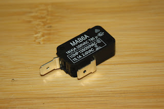
Here's a limit switch:
The limit switches are pretty much the same thing as the arcade button switches but are "normally closed" only while the arcade buttons could work either way. Limit switches are considered by some to be optional on such small equipment. I've read that other folks with steppers consider the steppers too weak to do damage as the motors will stall first. My motors are pretty beefy. Perhaps too strong for the mill. I don't know that they will do damage to the mill running into the hard stops, but I do know that I am likely to make mistakes and I'd like to take all reasonable safety moves.
When running a program, pressing any of the 6 directional buttons will "pause" the program. This will likely be a hard stop. This should be useful for situations where I'm not really sure I've set things up right but it's not an emergency. The buttons are polled in the main loop. It's possible, although unlikely that polling could miss a state change. As described above, I intend to hook up the limit switches to a hardware interrupt to avoid any delays or misses by the main loop polling. The limit switches are wired in series (normally closed) so any break in the path will trigger the shutdown.


