Monday, March 21, 2011

Fine Tuning Acceleration

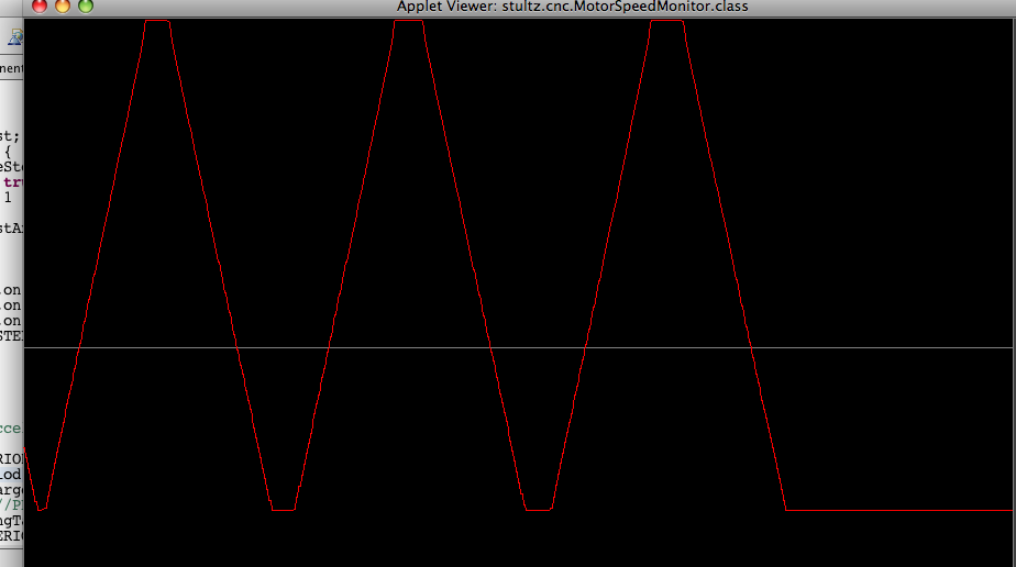
I added some sliders to my plotting program to allow me to make adjustments to the acceleration profile on the Arduino in real time. Last time I had added one "split point" to straighten out the top part of the graph. I added another split point so I have 4 points total, the minimum, upper split, lower split and maximum. Each point has a "delta" associated with it. When the period is at the lower split, the amount we change the period per step is the "lower split delta". So the per-step change is a mapping of period to delta, a blend of the 4 points. Here is a screenshot of the app showing a graph with slight easing at the start and end:


As I said before this is a very simple solution. Only 8 data points with 2 integer comparisons to make and one "map" function, also integer-based. Here's the code for the acceleration:

// perform constant acceleration
long change;
if (period < LSPLIT) change = map(period, MIN, LSPLIT, MIND, LSPLITD);
else if (period < USPLIT) change = map(period, LSPLIT, USPLIT, LSPLITD, USPLITD);
else change = map(period, USPLIT, MAX, USPLITD, MAXD);

if (period < targetPeriod) { // accelerating
period += change;
if (period > targetPeriod) period = targetPeriod;
if (period > MAX) period = MAX;
} else if (period > targetPeriod) { // decelerating
period -= change;
if (period < targetPeriod) period = targetPeriod;
if (period < MIN) period = MIN;
}
Timer1.setPeriod(period);

I've run it on the motors and it seems to work great. The acceleration factor is pretty low right now, I want time to be able to see it happen, but I'm sure there will be plenty of tweaking done to the values once the motors are installed on the mill.

Thursday, March 17, 2011

Naive Acceleration

Last post I wrote about how the motor action was not smooth. I made a number of guesses about what was wrong. I looked into resonance and was pretty sure that was it since my motors are just sitting on the bench and have no load on them. I also suspected my acceleration algorithm. Back in January I wrote about how I would handle acceleration in the host software. A graph of speed against time is a straight line. This is known as "constant acceleration". I figured I'd start with a certain large time value between steps and knock it down by a constant amount for each step taken until I got to the minimum time between steps. That constant amount is the "constant" in "constant acceleration", right? Not quite.

The RepRap project has several lineages of firmware doing GCode interpreting / stepper motor control. Most use a constant acceleration method. This page here describes approaches to acceleration:
The official FiveD firmware changes speed by a fixed amount each step, however this also alters the step time. Acceleration = dv/dt, so with a fixed dv but a changing dt, acceleration changes during a move. This makes high speeds quite unattainable as the acceleration quickly outstrips the motor's ability to keep up.
I'm pretty sure that's the problem I have going on. If the slowest speed has, say, 20,000 microseconds between steps and each step we knock off 1,000, eventually we'll work our way down to 2,000 microseconds between steps. Then we knock off 1,000 and *poof* we've just asked the stepper to double its speed in one step. I think that's a pretty easy way to see the problem. We know that an object in a vacuum falls at 9 something meters per second per second. A graph of time vs distance would be a logarithmic or exponential curve. We want a straight line. I kinda feel like an idiot now.


Here's the portion of the code which changes the speed:

// perform constant acceleration
if (period < targetPeriod) {
period += PER_STEP_PERIOD_CHANGE;
if (period > targetPeriod) period = targetPeriod;
if (period > MAX_PERIOD) period = MAX_PERIOD;
} else if (period > targetPeriod) {
period -= PER_STEP_PERIOD_CHANGE;
if (period < targetPeriod) period = targetPeriod;
if (period < MIN_PERIOD) period = MIN_PERIOD;
}
Timer1.setPeriod(period);

I wrote a Java/Processing app to graph the period. The above code looks like this:


You can see the sharp upward curve. Near top speed I'm asking the stepper to to make advances in speed that are very large compared to the current speed. (I'm really doing "speed" in the reverse, faster speeds are generated by shorter pauses between steps.)

The RepRap link above references another article here which seems to be what a lot of microcontrollers base linear acceleration on. There's a lot of fancy math symbols and stuff there. I made it through calculus in college but it wasn't easy. I'm not really motivated to work through it. I figured the RepRap firmware already has an implementation of this so I'd just rip it off. But it's not all that easy to wade through someone else's code. But then I got this idea. Rather than reduce the current period by a fixed amount per step, I'll reduce the period by a value that's proportional to the current period.


// perform constant acceleration
long change;
if (period > UPPER_PERIOD_SPLIT) change = map(period, MAX_PERIOD, UPPER_PERIOD_SPLIT, 500, 50);
else change = map(period, UPPER_PERIOD_SPLIT, MIN_PERIOD, 50, 1);
if (period < targetPeriod) {
period += change; //PER_STEP_PERIOD_CHANGE;
if (period > targetPeriod) period = targetPeriod;
if (period > MAX_PERIOD) period = MAX_PERIOD;
} else if (period > targetPeriod) {
period -= change; //PER_STEP_PERIOD_CHANGE;
if (period < targetPeriod) period = targetPeriod;
if (period < MIN_PERIOD) period = MIN_PERIOD;
}
Timer1.setPeriod(period);


This produces a graph like so:


That's a pretty straight line! You might notice the split thing. The straight map still produced a slight lift at the top end. I split the range to compress the values at the top and straighten it out. I tested it out this evening driving the real motors and it's quite nice. I have the 3 steppers on 3 different microstepping settings and all 3 run smoothly from stop to max. I could add a couple more split points and that would be enough to really tune it. Now I feel like a genius. The computational power required for this is very minimal. It seems to be working very well so maybe I'm being fooled by something.

Sunday, March 13, 2011

Manual Control Rough Build

I made some good progress over the last week or so. I've got all the buttons and the throttle control connected to the Arduino. It's pretty rough looking. I'm trying to pull lots of things together, the input controls connected to the controller and the firmware to respond to the input and move the motors.


I built the panel here pretty quickly. I wrote in a previous post how careful I have to be to avoid making mistakes when I'm building things. Norm Abram said, "Measure twice, cut once", right? He also said, "don't measure if you don't have to." If you need a board the same length as another, lay one over the other and mark the longer one to match the shorter. So I put the throttle control up to the right end and marked the board where the corners of the throttle line up and made square lines on the board. I marked the hole centers and drilled the holes. I went back to the throttle lines and baffoon that I am, I threw it on the band saw and cut to the lines. But the lines represented the "extents" of the top plate on the throttle. I was supposed to cut a smaller hole so the plate had something to sit on. That's what the ugly gap on the right is all about.

Then I went about soldering up a circuit board to connect the buttons and potentiometer to the microcontroller.


Yeah, that's pretty ugly. It's not nearly as easy to do this kind of soldering as it is a proper PCB. Believe it or not, there aren't any solder bridges here. In fact I had to troubleshoot a bad connection down one of the middle vertical lines. With the wires bridging each pad and piles of solder it was hard to tell there was half a bridge that didn't come down on the other side. I think I discovered this doing a continuity check early on but I didn't trust my meter. So I wasted some time pulling things apart to find the problem.

Once the inputs were all responding, I ran into another problem. When I built the opto-isolator circuit I did a nice wiring diagram but I didn't follow it opting instead to run the wires the easiest way. So I didn't know what Arduino pins mapped to what stepper driver pins. I had to modify the firmware to allow me to interactively set the mapping without multiple uploads.

I got the manual controls all working properly. That's pretty cool. But the motion of the motors is odd. At very low to moderate speeds, the acceleration algorithm seems to be good. But as it moves to higher speeds it gets jumpy and even stops momentarily. There could be a number of reasons for this. There could be a problem with the interrupt routine where the time it takes to execute the interrupt is longer than the time between steps. It could also be a problem with "resonance". I don't really have any experience with this, but the steppers can lock up at certain frequencies. The steppers are just sitting on my workbench, they aren't under load. It's possible putting some load on it may take care of the resonance.

It might also be my acceleration algorithm. The idea is pretty simple: the motor is turning at speed A and we want it to turn at speed B, so with each step we change the current speed by C, which is our acceleration constant. This seems to work well at low speeds but it may be too coarse at higher speeds or there might be some little error in calculations. I think I'll take a look at some of the RepRap GCode projects that also use constant acceleration.

One "interesting" thing that happened is that when I upload the firmware while the stepper controller is on, the X stepper goes nuts. The X step signal is on pin 0. This would be bad for a regular Arduino as pins 0 and 1 are serial lines. This is a Sanguino board which has serial lines on 8-11 (it has 2 serial ports). I'll have to look at the specs for the Sanguino or find someone who knows what's going on.

Monday, March 7, 2011

StepperDriver class

In my last post I wrote that I was going to be all patient and disciplined and write the communications protocol for the laptop talking to the Arduino. That didn't happen. After a little thought, I realized all I needed was to be able to set some of the key properties of the StepperDriver for testing purposes. I wanted to be able to set the maximum and minimum times between steps and the acceleration constant. (Yeah that sounds weird, changing the constant.) The Arduino project has a library available for simple messaging (called Messenger). It's not a 2-way protocol, it's just a simple way to send a "phrase" such as:

acc 5000

to the Arduino and "read" it with some simple parsing. Once the message is complete (a carriage return is encountered) a function is called and we can compare the first "word" with some command to set a property. Then we can read a number, in this case a 4-byte number (long). The above example sets the acceleration constant to 5000. Once the code was uploaded to the Arduino, I opened a serial terminal and I could easily type in the simple commands to read and write the properties.

So I jumped right into the code for the StepperDriver. Since I had already prototyped it in Java there wasn't a whole lot to the conversion. I struggled with a few things related to specifics of C and specifics of the Arduino, things I'm not yet experienced enough with. Other than that, the coding was pretty academic.

I've got my Bare Bones Board plugged into a prototype breadboard with 2 LEDs and 2 buttons plus a potentiometer. One LED is a stand-in for the direction pin, the other for the step pin. One button is for turning the motor in one direction, the other the other. The actual stepper motor would receive a very fast pulse train. For development, I scaled the timing way down so I could see the lights blinking.

I've got it all working with acceleration and "feed speed override" with the pot scaling the target speed. The StepperDriver simply "goes in the specified direction" while trying to make its speed the target speed by adjusting the current speed by the acceleration constant.

The next step is to put all 6 buttons and the throttle controller together and wire it all up to the real stepper driver.

Tuesday, March 1, 2011

Communications Protocol

I've got a few of the basic components working. I renamed InputPin/OutputPin to DigitalInput/DigitalOutput. I hooked up a couple of buttons and LEDs to the Arduino and I've got ButtonManager working nicely. I'd like to start on StepperDriver. That's going going to be super rewarding. I cleaned up my Java "simulation" of StepperDriver and I think the Arduino version will be easy enough. But eventually I need to communicate effectively with the Arduino from the laptop to set properties and issue commands. I'm building the manual controls first, but I think it will be easier to write StepperDriver if I can modify the state of the Arduino without having to constantly recompile and upload code to the Arduino.

I'm thinking there will be three things you can do:
Read a property
Write a property
Issue a command

Properties will certainly be all numbers. I can't see the need for any human-readable stuff, the host software can translate error codes, for example. I might need "boolean" values which could be represented with zero and one.

The Arduino supports byte, int, and long numbers. I plan to avoid any floating point numbers for performance reasons. Byte is one byte long, int is 2 bytes and long is 4 bytes. So a message will have an identifier (what property to set, what command to call) and 0, 1, 2, or 4 bytes of payload. Eventually I'll want a checksum or some other error correction.

The computer and the Arduino communicate with a Serial connection. I'd like to find a Serial communications protocol that is simple and robust and I don't want to get hung up building it myself. I've looked at Firmata, SNAP, basic MIDI, Modbus, and non-standard stuff. I can't seem to find anything I'm really happy with. I suspect I will do something based on MIDI, but for now I'm going with something very simple to get things going.

A favorite Object-Oriented Programming guideline of mine is "encapsulate the concept that varies". I expect to change the implementation of the serial communication protocol so I want to "wrap" it, or hide it from the main code. This means writing a Java class and a C++ class with an interface or "API" that is designed around the requirements of the "high-level" message format I described above and handles all the back and forth to the lower level serial protocol.