I got a piece of plexiglas cut to size at the local hardware store. I cut a slot in the center to accomodate the Y stepper and made some aluminum brackets. The mounting blocks are affixed to the counter top with screws and the brackets slide in a channel.
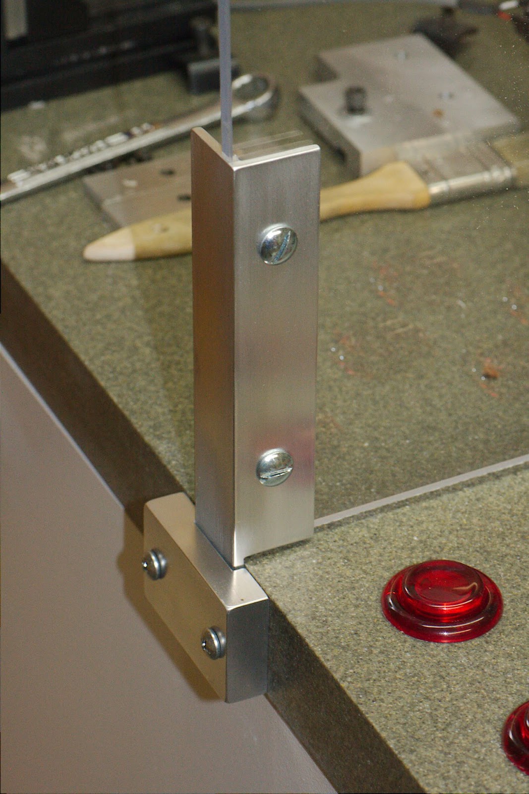
Machining is a practice where a high degree of accuracy is the goal and fairly easy to achieve with a decent mill. Working on larger projects, wood working, house building and so on isn't so accurate. Here, the countertop edges are not square with the surface and I didn't check it. With a good eye you can see the block, bracket and glass are not in line. I had to do a little rework to open the channel to allow it to move easily.
Here's a longer view. The glass is pretty clean.

I cut a slot in the front panel for the USB port. I made a template from scrap plexiglas and clamped it behind the surface you see here and used a 1/2" trim bit in my router. It was a bit tricky since the depth of cut was less than 1/2" and the material was 3/4" thick. It took several passes at multiple depths.

I produced a profiling GCode file in HeeksCAD for the "plug" to go in this hole. I had to implement arcs in my host program. I'm pretty happy with it. Here's a preview:

It's got a nice "roll on/off" in the lower left. I also put a "tag" in for fun that's in the lower center. I don't need it for this piece, I just wanted to see how it worked.
I've got a couple of decent geometry libraries available. For the arc implementation I needed to calculate the angle between three points. One available routine worked well for 3 out of 4 quadrants. Consider a point at 12 o'clock, the center of the clock another point and a third point at 3 o'clock. That's a 90 degree angle. If you are going clockwise, but a 270 degree angle the other way. The routine I tried seemed to recognize the orientation and produce 90 or 270 depending on the order of the points but it failed in one quadrant.
So I had to use a routine that always produces the smaller angle, in this case 90. I needed a way to determine if I needed to subtract the angle from 360 to get the oriented angle.
I got crafty and pulled this off by making a line segment from the first point to the third point. I found the midpoint and made another line segment from there to the center. The line segment objects I created have a method to compare itself to another line segment and determine if the other line is to the left or the right. If to one side I take the angle given, if to the other side I subtract the angle from 360.