Along the top is the DB-25 connector. The holes are a little over 0.100" apart but as you can see I have to get a trace in between each one. The traces in this illustration are 0.016" wide. I'm using a conical cutting bit and I don't know how deep I'll have to cut to isolate. Once I figure that out I'll be able to figure out how wide the cutting path will be. My concern is that I'll be cutting a path that's wider than the space between the traces and the traces will be too thin. Worse is that the pads will be too thin and I'll drill it all away.
The etchable design then goes through some manipulation to expand the elements to account for the width of the cutting bit. Then I export to GCode using a plug-in in Inkscape.
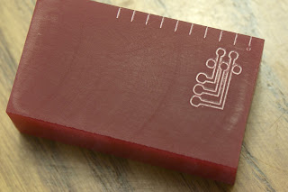
I mixed up a pot of plaster of paris and made a brick to do some practice cuts on. I don't have any pictures of it because it's not very impressive. I made up a test design that incorporates both the size and spacing of the DB-25 pads and traces plus standard 0.100" pads. I squared up a piece of cured polyurethane resin and cut the test path:
I arranged the path to make the pads and traces as large as possible, i.e., the path around the pads is more or less coincidental with the path along the traces between the pads. While is looks like it will isolate ok, it seems quite tight. The smallest drill bit I have is 1/32" which will probably create a hole around 0.050". I think that will wipe out the small holes on the DB-25 connector. Not good.
The three larger pads at the lower left are standard-size holes on 0.100" spacing. Or are they? I held up a standard header pin thingy against the three holes and they don't add up. ("Cat don't want to eat mice, wants dog to massacre him...") I wrote a quick program entirely in Java to cut the lines across the top at 0.100" intervals and they line up just right with the header. So something is wrong with my tool chain.
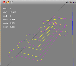
The good news it that the path is too small, so when it's fixed the pads and traces will hopefully be big enough to accommodate the 1/32" drill. I added a feature to the host software to calculate the extents of the mill movement, the minimum and maximum positions on each axis. Here's a screenshot of the SVG design. The page is sized to the path.
As you can see, the path area is 0.34 by 0.53. Here's the host software with the extents displayed:
The min X and Y are 0, the max are 0.273 by -0.425. It's 80% of actual size. I'll have a look at the plug-in for generating the GCode. Maybe there's some unit conversion error.


No comments:
Post a Comment