Tuesday, June 5, 2012

Cabinet Complete

Whew! The last few weeks have been crazy. I had to clean out my garage, set up my trailer for hauling sheet goods, transform the trailer into a work surface... I built the cabinet from 4x8 sheets of 3/4" MDF in the garage on the trailer. I don't really like doing woodworking any more. I just don't have a decent work space and most of my tools stink.

Anyway, here's the design again:


And here's the (nearly) finished cabinet:


MDF is like Super Cardboard. It wicks moisture like crazy and swells up. I got this great idea to seal the cabinet with a few coats of water-based polyurethane. The stuff I picked up is quite nice. It repels water nicely. It also repels latex paint. It took me a few extra passes of the primer paint to get full coverage. It kept beading up. It also looks like the paint is not bonded real well and it will chip easily. You can see several such chips in the picture above. Maybe that wasn't such a good idea. I'll do touch up paint when the whole thing is done.

The drawer design is super simple, the drawers are just open-top boxes riding on 1" rails glued to the sides of the cabinet. I rubbed paraffin wax on the contact surfaces and the slide action is quite nice.

I was worried about the rectangular cutouts in the counter top. I used a single straight edge carefully clamped. Only one of the four corners did I use an end stop on. The rest was just done very carefully. I took my time and nudged things ever so slightly to get the cut I needed. I practiced on the speed control first since it wasn't critical then did the DRO cut out. The DRO sits flush with the counter top. Here's a pic:


I'm VERY happy with it. It's perfect. Here's a closer shot (click for larger view):


The corners on the DRO are 1/4" radius and I happened to have a 1/2" trim bit for my router.

Here's a shot of the power strip / surge protector on the front:


While I struggled with a few different techniques to do the cutout it came out very nice in the end. I did this cutout before the counter top and I was afraid the router technique would be unwieldy, but it worked out fine.

I made my usual fare of mistakes, mostly craftsmanship, a mental error, a design error. Most mistakes are well hidden. The one design error was that I didn't allow any overlap of the ends of the counter top. It should extend 1/4" off either end to account for inexactitudeness of the cabinet. Instead I built it flush and the cabinet is not perfect leaving under hang visible in the upper right corner of the top photo. I'm pretty sure I'll make some chip guards which will give me a chance to cover it up.

I drilled and tapped holes to secure the mill to the table and cut a 1" slot in the center of the counter top under the mill to run wires through. Next is some sanding work on the counter top, secure the counter to the cabinet, then start wiring things up!

Monday, April 23, 2012

Cabinet Progressing

I drilled holes and rough-cut rectangles for the controls in the counter top. Here's a test-fit of the controls in the right corner:


I'm not crazy about the look of the controls on the granite-like finish of the countertop. I might paint a fancy design on the front 6 inches.

I need to make a jig for my router to do the finish cut on the rectangle cut-out that will hold the DRO. It's critical that I get this right, because there is no overlap, it's a flush fit. Here are a couple shots of the full cabinet design. This is done in SketchUp. 


I'm working on the cut list. It looks like it will take almost 1 1/2 sheets of MDF. I was hoping to do it with one sheet, but the drawers add quite a bit.

Saturday, March 31, 2012

Cabinet and Work Surface

I forgot to post a couple pics earlier. This is the junction box for the limit switches. First the inside, the soldering isn't finished in this shot. The grounds still need to be joined and then the perf board pressed in and glued:


Here's the outside. Sorry about the focus. The light isn't great for photography and I'm a bit lazy with it.


After wiring up the controller I went crazy and rerouted the speed controller for the spindle motor. I also disconnected the thermal cutoff switch from the motor control and connected it to my microcontroller. Rather than shut the motor down it triggers an audible alarm.

Here's a before shot of the mill. The speed control is the box to the right of the spindle and below the motor. If you can figure out where those things are.


And here it is with the speed controller missing. This angle shows a significant improvement in visibility of the work area. Plus, the controls will be with all the others. I used a film canister as the junction box.


Earlier I posted someone else's cabinet for a mill-in-a-box. I thought I'd do something similar. The box would serve to hold tools, keep dust off the machine, and protect it from swinging 2x4's. But then I started making measurements and realized the part of the cabinet above the work surface was going to be huge, a 24" cube. That's going to be heavy. I got a bit concerned about my ability to build something sturdy enough to handle the weight. Then I called a contractor buddy of mine to see if he had a source for scrap counter top. It just so happened he was doing a kitchen job later in the week and pulling out a Corian solid-surface counter top. I pulled this piece out of his dump trailer:


It's a neutral grey, kind of speckled like granite but nothing warm and flowery. Not that there's anything wrong with that. Just not what I want in my shop. This piece is 30" wide and 25" deep. It even has a backsplash. I was going to build a worksurface 24" x 24" so this is a little bigger. But with the mill sitting on it, it doesn't look that too big (the work surface). The white card stock in the foreground are stand-ins for my controls. I've even got room for the DRO.

So I think I'm going to bail on "enclosing" it. I can always add that later. This material may be a bit hard to work. I've got to drill a number of large holes and cut out rectangles for the DRO and throttle. I'll take my time, hopefully won't screw it up.


Saturday, March 24, 2012

PCB Wiring Complete

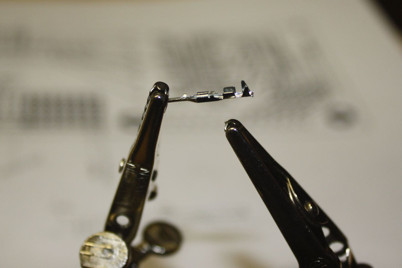
I've completed the wiring for the new controller board. It's not pretty, but it's going to be hidden anyway. The important thing is that the connections are good and robust (they won't pull apart). A lot of the work was soldering connectors on the wires. Here's a shot of one such (male) connector:


There are 2 pairs of protrusions on the right for crimping the wire with. The right-most pair tends to get caught going into the housing, so since I was soldering I clipped it off:
 

Here's a shot of it soldered:


Most of the connectors I did were female. Occasionally I'd hit it with a little too much heat and solder and it would wick up the connector leaving enough solder in the channel to block the male connector. All in all it went just fine. Here's a shot of the new rats nest. It actually looks better than the prototype:


And a close up. It's not as well organized as I'd like but it's pretty good.


I did make a mistake in the design, though. The Sanguino has 2 pairs of serial lines. The actual port I use to connect to the computer is doubled by pins 8 and 9. Pins 10 and 11 are the other set of Rx/Tx lines. I wired all the lights to pins 8-13. This means 2 of my lights did not work since they were connected to the primary serial port lines (they flashed when I uploaded the firmware). Pins 8 and 9 are clearly labeled as Rx/Tx. Pins 10 and 11 are labeled as Rx2/Tx2 but the letters are very small and hard to make out. I must have been thinking that the clearly-labeled RxTx was the secondary serial port and since I'm not using it I could use it for lights.

I was smart enough to pull out all pins to the Sanguino. Pin 7 was designated as an extra output pin and pin 14 was designated as the piezo buzzer (alarm). Pin 14 was selected because it's a PWM-capable line (and it was at the end of the row after the lights). So I've re-routed 8 and 9 to 7 and 14. I moved the buzzer over to one of the extra A/D lines. What I've lost is the ability to use PWM to drive the alarm which would have supported multiple tones. Now I'll have just on and off. The alarm will sound when the mill motor overheats which should never happen, so I think I can live with a simple alarm sound.

Monday, March 5, 2012

PCB Assembled

I week delay due to vacation. I admit a Disney cruise is more fun than building robots. As soon as I got back I soldered the components on the board, cleaned it up and tested it.

Here it is with everything soldered on:


And with the components plugged in:


The DB-25 plugs in (via cable) to the stepper driver box. I plugged it in and tested it. The lights and buttons aren't connected, so I used a couple of test leads to turn on the limit pin and then tag the button pins. After some tweaks to the firmware to support a different arrangement of pins for the stepper motors the mill moved just fine in manual and program mode.

The next step is to make some cables and connectors for the controls. I need to give some serious thought to the cabinet and control panel layout so I can make wires and such the right length. I'm imagining an arcade-like cabinet to go with my arcade buttons and throttle controller. Not sure I can pull that off since I need to support a mill with open access.


Here's a cabinet I like for the top part:


I'd like all the features of the above. I need to figure out how I'm going to integrate the controls into this. Under the work surface will be a shelf or two for the electronics, the stepper controller box, transformer, power strip / surge protector, etc. I'll probably use the very bottom for material storage. I'll probably make it out of MDF. I want it to look cool but I want it easy to build. I'll use biscuits for joining instead of dados, rabbets, etc.

One feature I want not shown above, I hope to add some rigidity to the Z column. I need to design a spine in the center rear panel that can connect to the Z column. It has to be rigid of course, but I'd like it to double as a cable chase.

I might try to use Google Sketchup to design this. I have a lot of experience with 3D tools for animation and graphics. Sketchup has some very nice CAD features but has some concepts I'm not used to. I may end up with simple pencil sketch designs.


Wednesday, February 22, 2012

PCB Arrived!

I finished the spiral pocketing operation and also wrote a spiral plunge operation to precede it. I'm starting to get a pretty good idea of how the host software design should be. I've created a "ToolPathBuilder" as a generic operation that I'll make various specific operations from. I've got a RectangularPocket which makes use of a SpiralPlunge:


Here is a test cut in my glue and plaster material:


And cutting the pocket in the RenShape material:


Here is the finished cut:


This will be a junction box for the limit switches. There will be three lines coming in from each side and one from the top.

Ok that was all very exciting. Here's the top news story: I got my PCB board back from Fritzing Fab! It's beautiful:


Definitely click to see the bigger picture. The logo didn't come out quite right, it was supposed to have a circle like the image in the upper left of this blog. Maybe my graphic wasn't quite right. Perhaps it supports objects converted to paths only, rather than a circle. It was just for fun anyway. I tested the pad wiring with my multi-meter on continuity. It looks just fine. I'm going on vacation in a couple of days, so soldering it up will have to wait. Very exciting.


Sunday, February 12, 2012

Area Strategy

I've started rewiring things in preparation for the new control panel board. I don't want to do too much because I'll eventually get to the point where I disable the mill and as soon as I do that, I'll need it to make something. I'd like to test the new board before disabling the mill, and even then I'll do it in such a way that it won't be terribly difficult to restore the current circuitry if the new board has a major problem.

I pulled the limit switches off and rewired them with the new shielded cable I got to fix the noise problems. I need a junction box to connect all the wires in. I have a huge chunk of RenShape from which I thought I'd make the box. The box design is very simple, 2" x 2 1/4" x 1/2" with a large pocket and a few holes coming in from the sides to insert the wires into.

Now I could write a routine to do a rectangular pocket easy enough, even a circular pocket. If you've ever done any Turtle Graphics programming you can see how I'd do it. But eventually I'm going to need to mill pockets in arbitrary shapes. A spiral cutting pattern from inside to out makes for a pretty efficient strategy. To do this I need to create a series polygons inset within the shape. This sort of thing has been done many times by others and there is no need for me to do it again. I spent most of the afternoon looking for a Java library for 2D geometry. The Toxiclibs library I'm doing the 3D work with has 2D functions but I couldn't find an inset (also known as a buffer).

I found the JTS Topology Suite. I imagine JTS stands for Java Topology Suite which means the full name is Java Topology Suite Topology Suite. I suppose it's like saying you are going to get money from the ATM machine. Anyway, I found it fairly easy to get started with the offsets I needed:


The blue line is the area to be machined. I've drawn a line on top of the blue one by creating an outset from the first inset. This gives the rounded corners and helps visualize the area that will actually be cut by the mill. The yellow circle represents the cutting head. I generated insets of a fixed distance until the last inset no longer fully encloses the mill cutter.

It should be easy enough to connect these insets in a spiral shape. I think I'll start with a spiral circle twice the size of the cutting head and plunge into it.

This will give me a generic spiral area function with broad applications. 

[Update #1]

I converted the insets into a spiral path. This wasn't as easy at is seemed because the relative start points of each inset were not aligned. So long as the next inset had the same number of points as the previous inset it was fine, but when the next inset drops a point (from 4 to three in this case) the start point "changed position" and messed up the continuity of the spiral. So I wrote a function to "align" the start points. This turned out to be pretty easy because JTS provides a tool to find the closest points between 2 objects. So the start point of the outer inset was compared to the inner inset to get the closest point. Then I just shifted the points in the sequence by the index of the closest point. Then I connected all the points from inside to outside: