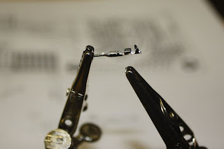
There are 2 pairs of protrusions on the right for crimping the wire with. The right-most pair tends to get caught going into the housing, so since I was soldering I clipped it off:
Here's a shot of it soldered:
Most of the connectors I did were female. Occasionally I'd hit it with a little too much heat and solder and it would wick up the connector leaving enough solder in the channel to block the male connector. All in all it went just fine. Here's a shot of the new rats nest. It actually looks better than the prototype:
And a close up. It's not as well organized as I'd like but it's pretty good.
I did make a mistake in the design, though. The Sanguino has 2 pairs of serial lines. The actual port I use to connect to the computer is doubled by pins 8 and 9. Pins 10 and 11 are the other set of Rx/Tx lines. I wired all the lights to pins 8-13. This means 2 of my lights did not work since they were connected to the primary serial port lines (they flashed when I uploaded the firmware). Pins 8 and 9 are clearly labeled as Rx/Tx. Pins 10 and 11 are labeled as Rx2/Tx2 but the letters are very small and hard to make out. I must have been thinking that the clearly-labeled RxTx was the secondary serial port and since I'm not using it I could use it for lights.
I was smart enough to pull out all pins to the Sanguino. Pin 7 was designated as an extra output pin and pin 14 was designated as the piezo buzzer (alarm). Pin 14 was selected because it's a PWM-capable line (and it was at the end of the row after the lights). So I've re-routed 8 and 9 to 7 and 14. I moved the buzzer over to one of the extra A/D lines. What I've lost is the ability to use PWM to drive the alarm which would have supported multiple tones. Now I'll have just on and off. The alarm will sound when the mill motor overheats which should never happen, so I think I can live with a simple alarm sound.


No comments:
Post a Comment