Wednesday, December 26, 2012

Way and Screw Cover

I visited a friend of my father over Thanksgiving break. He has a rather extensive machine shop in his basement. This guy is good. He builds his own telescopes. So what, right? You went to a meeting of the local astronomy club and some guy had a plywood stand with a cardboard Sonotube and some optics, and bam! he's built his own telescope, right? You could do that.

No. This was different. This guy grinds his own optics. I didn't see any mirrors he made but I wouldn't be surprised if he could do that, too.

Anyway, he squared up a large piece of stock of mine to be made into a tooling plate. I'll get to that in another post. He also gave me some vinyl from a shower pan liner or something. He suggested I use it to make way and screw covers. The Y-axis is pretty exposed on the Sherline so I thought I'd give it a try.

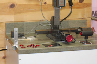
The front side of the machine is easy. It's "open ended" so easy enough to add mounting material to hold the cover. Here's a shot of the front piece I made:


I used this huge piece of Corian solid-surface counter top for the material. It's plastic. It's machines pretty nicely although it gets a little stinky if it heats up too much. It doesn't look very good, however. It's kind of poor simulation of granite or something. So I just painted it with a flat black and buffed it a bit. It fits right in with the anodized black aluminum of the machine. Ok, the piece I made has the 3 screws on top. Of course I used my hot glue gun to mount it. 


Here's the first of three attempts to design a mount for the rear. The challenge with the rear is that anything attached to the rear reduces the range of motion. Above I added the mounting pieces outside the rear column. Theoretically the cover would fold up on itself once and compress against the column costing only 80 mils of Y-travel. I attached the vinyl sheet so it folded up against the table. This resulted in the vinyl arching down against the screw. As the table moved to the rear, the downward bow became strong enough to stall the stepper motor.

Here's the third attempt:


The second attempt had no support in the middle and the vinyl dipped down creating a path for swarf right down to the screw/way. The third design is just one piece with a thin bridge to provide support. So I'm losing about 1/4" of travel at the rear.

Here it is with both covers in place:


And an engraving operation with the covers doing their job:


(Yes, that's a drill chuck. Yes, I know I'm not supposed to use it for milling, but I bought a Dremel engraving kit assuming the shanks were all 1/8". Turned out half of them are 3/32" and I don't have a collet that size. This is a pretty light engraving cut so it should be OK.)

Sunday, December 2, 2012

USB Port Installed

I think it's fair to say this project is done. The system is fully operational. I made 3 parts to secure the USB port. Here's a screenshot of the CAD design for the part that holds the end of the board where the USB cable plugs in. I forgot to take a picture of it.


The fit of the USB board is real nice. I had to file the cabinet opening a bit, then I tapped the part in and it's quite snug. Then I made 2 parts to secure the board in the inside:


I just used some scrap material for this. The plexiglas machines quite nicely I think.

I did the CAD design above in ViaCAD. I'm running the trial copy of the 2D/3D version. I'm quite impressed by the product. It's quite advanced, as far as I know. I was pretty happy with QCad and ViaCAD blows it away. It's also very reasonably priced at $100. I got it 20% off.

I generated the tool path with HeeksCAD. My impression of HeeksCAD seems to degrade the more I work with it. I had high hopes initially. Same goes for PyCAM. PyCAM was supposed to release a significant version a year ago. I find the current release pretty unworkable since I'm not needing full 3D paths and PyCAM's pocketing is very basic.

There are some CAM libraries written in C/C++ but I can't figure out how to leverage them in my project. I wrote a basic pocketing routine a year or so ago using the Java Topology Suite. It looks like I'm going to have to pick that up again and see about reading in a DXF file to generate profile, engraving, and pocketing paths.

Saturday, November 17, 2012

Chip guard

I stated previously the next step was to make some sort of mounting block for the USB port. I was doing some test work on some plaster/glue material and I discovered pretty quickly how dirty my controls would get. I figured I would make a chip guard eventually but after some debris got caught in a couple of buttons in the ON position I changed my priorities.

I got a piece of plexiglas cut to size at the local hardware store. I cut a slot in the center to accomodate the Y stepper and made some aluminum brackets. The mounting blocks are affixed to the counter top with screws and the brackets slide in a channel.


Machining is a practice where a high degree of accuracy is the goal and fairly easy to achieve with a decent mill. Working on larger projects, wood working, house building and so on isn't so accurate. Here, the countertop edges are not square with the surface and I didn't check it. With a good eye you can see the block, bracket and glass are not in line. I had to do a little rework to open the channel to allow it to move easily.

Here's a longer view. The glass is pretty clean.


I cut a slot in the front panel for the USB port. I made a template from scrap plexiglas and clamped it behind the surface you see here and used a 1/2" trim bit in my router. It was a bit tricky since the depth of cut was less than 1/2" and the material was 3/4" thick. It took several passes at multiple depths.


I produced a profiling GCode file in HeeksCAD for the "plug" to go in this hole. I had to implement arcs in my host program. I'm pretty happy with it. Here's a preview:


It's got a nice "roll on/off" in the lower left. I also put a "tag" in for fun that's in the lower center. I don't need it for this piece, I just wanted to see how it worked.

I've got a couple of decent geometry libraries available. For the arc implementation I needed to calculate the angle between three points. One available routine worked well for 3 out of 4 quadrants. Consider a point at 12 o'clock, the center of the clock another point and a third point at 3 o'clock. That's a 90 degree angle. If you are going clockwise, but a 270 degree angle the other way. The routine I tried seemed to recognize the orientation and produce 90 or 270 depending on the order of the points but it failed in one quadrant.

So I had to use a routine that always produces the smaller angle, in this case 90. I needed a way to determine if I needed to subtract the angle from 360 to get the oriented angle.

I got crafty and pulled this off by making a line segment from the first point to the third point. I found the midpoint and made another line segment from there to the center. The line segment objects I created have a method to compare itself to another line segment and determine if the other line is to the left or the right. If to one side I take the angle given, if to the other side I subtract the angle from 360.


Sunday, October 7, 2012

Recoded host

I haven't made anything yet. That's a bit of a bummer. I decided to re-write the host software in Scala. I wanted to learn the language and there's no better way than to dive in to a real project. Pecking away at examples in a book doesn't lead to strong retention of concepts. I'm a veteran Java coder but I have a feeling Scala will take over soon.

The Java host program was a bit messy. A lot of it was experimental. I had to find out real quick like if I could do a number of things I hadn't done before because I knew I was going to be writing a lot of the code. I want to drive the system from a Mac and there just isn't enough related software for it.

So the Scala rework gave me an opportunity to clean up a lot of it. It's much better organized with a number of interdependencies removed. I also wrote a new "procedure" for facing a block of material. Here's a screen shot of a "box-in face" tool path:


Next up will be procedures to edge the material, also part of "squaring up" the stock. Then a procedure to cut a channel which might also be called a groove, except that it's wide. I also need drilling procedures. I think I'll throw in a rounded-corner procedure for fun. That will give me all I need for the parts I need to mount the USB connector.

Wednesday, July 18, 2012

It's Done!

Ok, the title of this post needs qualification. This project will never be done. There will always be room for improvement and of course there's plenty to do on the software, but the hardware looks done. From a distance.


If you look carefully, you can see the USB board sticking out at the lower left of the countertop. I didn't  design in any way to mount it. On purpose. I need the mill working in order to machine an appropriate mount. It's easiest to drill a big hole in the face of the top drawer face so I figure I'll make something out of plastic that secures the board within a round plug of some kind. Then I'll have a nice USB port right on the front panel. Nice.

Here are some more pics of the assembly process.


Here's a ghetto-style box for the spindle speed controller. The SC is in the upper right. That's duct work left over from remodeling with, appropriately enough, duct tape holding it together. I'm hiding the whole thing inside the cabinet, so I don't care much how it looks. The metal box is grounded and intended to capture noise from the SC.


The wiring took me a long time to finish. Most of the wires connecting to the microcontroller weren't long enough, at least not for comfort. I think I planned for a cabinet of 24" in width, then I got the 30" countertop and didn't increase the wire lengths accordingly. I can't even remember if I made the wires before or after I got the countertop.

In an early test of the wiring hookups I had a little problem. I have a button input for the thermal switch. One thing I did well in my design of the microcontroller breakout board was to pull out all the pins. I allowed for the extra pins to be easily wired as output with spots for resistors. I did not provide for input by making connections for resistors to pull to ground. So I contrived a 3-pin connector for the thermal cutoff switch that has a 10K Ohm resistor "inline". Here's a picture with the heat shrink tubing pulled back.


After connecting it together, I powered things up. Wiggling the connector resulted in the green LED of the Sanguino going out. I didn't know what that meant, but the microcontroller wouldn't work when the light was out, so it certainly wasn't good. I stepped back and scratched my head to think a bit when I noticed a smell. Not a good sign so I powered down quickly. I started manipulating various wires and I brushed my finger across the 5V regulator package and burned my finger!

The regulator on the Sanguino is not supposed to get hot, the overall draw is quite low. This had to mean I had a short. I removed the thermal shutoff input and the buzzer output and powered up. The system worked fine. So I tore apart the thermal shutoff input and discovered what you see above. Manipulating the connector resulted in the two leads of the resistor coming together and shorting power to ground. Not good. I spent quite a bit of time reworking this connector. It was painful.

Anyway, it's all good now. Fully operational. I've started moving things into the drawers. The paint is going to be a pain. It chips very easily and the color is too light, it will get dirty fast.

Time to clean up my shop, something I've refused to do for about 20 months until this was done.

Tuesday, June 5, 2012

Cabinet Complete

Whew! The last few weeks have been crazy. I had to clean out my garage, set up my trailer for hauling sheet goods, transform the trailer into a work surface... I built the cabinet from 4x8 sheets of 3/4" MDF in the garage on the trailer. I don't really like doing woodworking any more. I just don't have a decent work space and most of my tools stink.

Anyway, here's the design again:


And here's the (nearly) finished cabinet:


MDF is like Super Cardboard. It wicks moisture like crazy and swells up. I got this great idea to seal the cabinet with a few coats of water-based polyurethane. The stuff I picked up is quite nice. It repels water nicely. It also repels latex paint. It took me a few extra passes of the primer paint to get full coverage. It kept beading up. It also looks like the paint is not bonded real well and it will chip easily. You can see several such chips in the picture above. Maybe that wasn't such a good idea. I'll do touch up paint when the whole thing is done.

The drawer design is super simple, the drawers are just open-top boxes riding on 1" rails glued to the sides of the cabinet. I rubbed paraffin wax on the contact surfaces and the slide action is quite nice.

I was worried about the rectangular cutouts in the counter top. I used a single straight edge carefully clamped. Only one of the four corners did I use an end stop on. The rest was just done very carefully. I took my time and nudged things ever so slightly to get the cut I needed. I practiced on the speed control first since it wasn't critical then did the DRO cut out. The DRO sits flush with the counter top. Here's a pic:


I'm VERY happy with it. It's perfect. Here's a closer shot (click for larger view):


The corners on the DRO are 1/4" radius and I happened to have a 1/2" trim bit for my router.

Here's a shot of the power strip / surge protector on the front:


While I struggled with a few different techniques to do the cutout it came out very nice in the end. I did this cutout before the counter top and I was afraid the router technique would be unwieldy, but it worked out fine.

I made my usual fare of mistakes, mostly craftsmanship, a mental error, a design error. Most mistakes are well hidden. The one design error was that I didn't allow any overlap of the ends of the counter top. It should extend 1/4" off either end to account for inexactitudeness of the cabinet. Instead I built it flush and the cabinet is not perfect leaving under hang visible in the upper right corner of the top photo. I'm pretty sure I'll make some chip guards which will give me a chance to cover it up.

I drilled and tapped holes to secure the mill to the table and cut a 1" slot in the center of the counter top under the mill to run wires through. Next is some sanding work on the counter top, secure the counter to the cabinet, then start wiring things up!

Monday, April 23, 2012

Cabinet Progressing

I drilled holes and rough-cut rectangles for the controls in the counter top. Here's a test-fit of the controls in the right corner:


I'm not crazy about the look of the controls on the granite-like finish of the countertop. I might paint a fancy design on the front 6 inches.

I need to make a jig for my router to do the finish cut on the rectangle cut-out that will hold the DRO. It's critical that I get this right, because there is no overlap, it's a flush fit. Here are a couple shots of the full cabinet design. This is done in SketchUp. 


I'm working on the cut list. It looks like it will take almost 1 1/2 sheets of MDF. I was hoping to do it with one sheet, but the drawers add quite a bit.

Saturday, March 31, 2012

Cabinet and Work Surface

I forgot to post a couple pics earlier. This is the junction box for the limit switches. First the inside, the soldering isn't finished in this shot. The grounds still need to be joined and then the perf board pressed in and glued:


Here's the outside. Sorry about the focus. The light isn't great for photography and I'm a bit lazy with it.


After wiring up the controller I went crazy and rerouted the speed controller for the spindle motor. I also disconnected the thermal cutoff switch from the motor control and connected it to my microcontroller. Rather than shut the motor down it triggers an audible alarm.

Here's a before shot of the mill. The speed control is the box to the right of the spindle and below the motor. If you can figure out where those things are.


And here it is with the speed controller missing. This angle shows a significant improvement in visibility of the work area. Plus, the controls will be with all the others. I used a film canister as the junction box.


Earlier I posted someone else's cabinet for a mill-in-a-box. I thought I'd do something similar. The box would serve to hold tools, keep dust off the machine, and protect it from swinging 2x4's. But then I started making measurements and realized the part of the cabinet above the work surface was going to be huge, a 24" cube. That's going to be heavy. I got a bit concerned about my ability to build something sturdy enough to handle the weight. Then I called a contractor buddy of mine to see if he had a source for scrap counter top. It just so happened he was doing a kitchen job later in the week and pulling out a Corian solid-surface counter top. I pulled this piece out of his dump trailer:


It's a neutral grey, kind of speckled like granite but nothing warm and flowery. Not that there's anything wrong with that. Just not what I want in my shop. This piece is 30" wide and 25" deep. It even has a backsplash. I was going to build a worksurface 24" x 24" so this is a little bigger. But with the mill sitting on it, it doesn't look that too big (the work surface). The white card stock in the foreground are stand-ins for my controls. I've even got room for the DRO.

So I think I'm going to bail on "enclosing" it. I can always add that later. This material may be a bit hard to work. I've got to drill a number of large holes and cut out rectangles for the DRO and throttle. I'll take my time, hopefully won't screw it up.


Saturday, March 24, 2012

PCB Wiring Complete

I've completed the wiring for the new controller board. It's not pretty, but it's going to be hidden anyway. The important thing is that the connections are good and robust (they won't pull apart). A lot of the work was soldering connectors on the wires. Here's a shot of one such (male) connector:


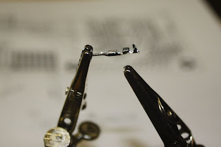
There are 2 pairs of protrusions on the right for crimping the wire with. The right-most pair tends to get caught going into the housing, so since I was soldering I clipped it off:
 

Here's a shot of it soldered:


Most of the connectors I did were female. Occasionally I'd hit it with a little too much heat and solder and it would wick up the connector leaving enough solder in the channel to block the male connector. All in all it went just fine. Here's a shot of the new rats nest. It actually looks better than the prototype:


And a close up. It's not as well organized as I'd like but it's pretty good.


I did make a mistake in the design, though. The Sanguino has 2 pairs of serial lines. The actual port I use to connect to the computer is doubled by pins 8 and 9. Pins 10 and 11 are the other set of Rx/Tx lines. I wired all the lights to pins 8-13. This means 2 of my lights did not work since they were connected to the primary serial port lines (they flashed when I uploaded the firmware). Pins 8 and 9 are clearly labeled as Rx/Tx. Pins 10 and 11 are labeled as Rx2/Tx2 but the letters are very small and hard to make out. I must have been thinking that the clearly-labeled RxTx was the secondary serial port and since I'm not using it I could use it for lights.

I was smart enough to pull out all pins to the Sanguino. Pin 7 was designated as an extra output pin and pin 14 was designated as the piezo buzzer (alarm). Pin 14 was selected because it's a PWM-capable line (and it was at the end of the row after the lights). So I've re-routed 8 and 9 to 7 and 14. I moved the buzzer over to one of the extra A/D lines. What I've lost is the ability to use PWM to drive the alarm which would have supported multiple tones. Now I'll have just on and off. The alarm will sound when the mill motor overheats which should never happen, so I think I can live with a simple alarm sound.

Monday, March 5, 2012

PCB Assembled

I week delay due to vacation. I admit a Disney cruise is more fun than building robots. As soon as I got back I soldered the components on the board, cleaned it up and tested it.

Here it is with everything soldered on:


And with the components plugged in:


The DB-25 plugs in (via cable) to the stepper driver box. I plugged it in and tested it. The lights and buttons aren't connected, so I used a couple of test leads to turn on the limit pin and then tag the button pins. After some tweaks to the firmware to support a different arrangement of pins for the stepper motors the mill moved just fine in manual and program mode.

The next step is to make some cables and connectors for the controls. I need to give some serious thought to the cabinet and control panel layout so I can make wires and such the right length. I'm imagining an arcade-like cabinet to go with my arcade buttons and throttle controller. Not sure I can pull that off since I need to support a mill with open access.


Here's a cabinet I like for the top part:


I'd like all the features of the above. I need to figure out how I'm going to integrate the controls into this. Under the work surface will be a shelf or two for the electronics, the stepper controller box, transformer, power strip / surge protector, etc. I'll probably use the very bottom for material storage. I'll probably make it out of MDF. I want it to look cool but I want it easy to build. I'll use biscuits for joining instead of dados, rabbets, etc.

One feature I want not shown above, I hope to add some rigidity to the Z column. I need to design a spine in the center rear panel that can connect to the Z column. It has to be rigid of course, but I'd like it to double as a cable chase.

I might try to use Google Sketchup to design this. I have a lot of experience with 3D tools for animation and graphics. Sketchup has some very nice CAD features but has some concepts I'm not used to. I may end up with simple pencil sketch designs.


Wednesday, February 22, 2012

PCB Arrived!

I finished the spiral pocketing operation and also wrote a spiral plunge operation to precede it. I'm starting to get a pretty good idea of how the host software design should be. I've created a "ToolPathBuilder" as a generic operation that I'll make various specific operations from. I've got a RectangularPocket which makes use of a SpiralPlunge:


Here is a test cut in my glue and plaster material:


And cutting the pocket in the RenShape material:


Here is the finished cut:


This will be a junction box for the limit switches. There will be three lines coming in from each side and one from the top.

Ok that was all very exciting. Here's the top news story: I got my PCB board back from Fritzing Fab! It's beautiful:


Definitely click to see the bigger picture. The logo didn't come out quite right, it was supposed to have a circle like the image in the upper left of this blog. Maybe my graphic wasn't quite right. Perhaps it supports objects converted to paths only, rather than a circle. It was just for fun anyway. I tested the pad wiring with my multi-meter on continuity. It looks just fine. I'm going on vacation in a couple of days, so soldering it up will have to wait. Very exciting.


Sunday, February 12, 2012

Area Strategy

I've started rewiring things in preparation for the new control panel board. I don't want to do too much because I'll eventually get to the point where I disable the mill and as soon as I do that, I'll need it to make something. I'd like to test the new board before disabling the mill, and even then I'll do it in such a way that it won't be terribly difficult to restore the current circuitry if the new board has a major problem.

I pulled the limit switches off and rewired them with the new shielded cable I got to fix the noise problems. I need a junction box to connect all the wires in. I have a huge chunk of RenShape from which I thought I'd make the box. The box design is very simple, 2" x 2 1/4" x 1/2" with a large pocket and a few holes coming in from the sides to insert the wires into.

Now I could write a routine to do a rectangular pocket easy enough, even a circular pocket. If you've ever done any Turtle Graphics programming you can see how I'd do it. But eventually I'm going to need to mill pockets in arbitrary shapes. A spiral cutting pattern from inside to out makes for a pretty efficient strategy. To do this I need to create a series polygons inset within the shape. This sort of thing has been done many times by others and there is no need for me to do it again. I spent most of the afternoon looking for a Java library for 2D geometry. The Toxiclibs library I'm doing the 3D work with has 2D functions but I couldn't find an inset (also known as a buffer).

I found the JTS Topology Suite. I imagine JTS stands for Java Topology Suite which means the full name is Java Topology Suite Topology Suite. I suppose it's like saying you are going to get money from the ATM machine. Anyway, I found it fairly easy to get started with the offsets I needed:


The blue line is the area to be machined. I've drawn a line on top of the blue one by creating an outset from the first inset. This gives the rounded corners and helps visualize the area that will actually be cut by the mill. The yellow circle represents the cutting head. I generated insets of a fixed distance until the last inset no longer fully encloses the mill cutter.

It should be easy enough to connect these insets in a spiral shape. I think I'll start with a spiral circle twice the size of the cutting head and plunge into it.

This will give me a generic spiral area function with broad applications. 

[Update #1]

I converted the insets into a spiral path. This wasn't as easy at is seemed because the relative start points of each inset were not aligned. So long as the next inset had the same number of points as the previous inset it was fine, but when the next inset drops a point (from 4 to three in this case) the start point "changed position" and messed up the continuity of the spiral. So I wrote a function to "align" the start points. This turned out to be pretty easy because JTS provides a tool to find the closest points between 2 objects. So the start point of the outer inset was compared to the inner inset to get the closest point. Then I just shifted the points in the sequence by the index of the closest point. Then I connected all the points from inside to outside:


Sunday, February 5, 2012

Micro Stepping

I finished my new board design and sent it off to Fritzing Fab. The turnaround is slow, for sure. They collect many designs and batch them together to reduce costs. This is a 2-sided board with solder mask and silkscreen. It's 2"x4.5" and costs a total of $62. I think that's pretty good. Here it is:


I'm particularly pleased with the logo. Hopefully the design is right, too. I looked it over a bajillion times.

While I'm waiting, I thought I'd do some more testing. I have noticed in some of my previous test runs of the PCB trace that the spindle wasn't ending exactly where it started. Or so it seemed. There is plenty of room in the software stack for error, but I was sure I had run a 50-minute program some time ago that ended exactly right.

One issue that could result in a real movement error (other than software) is stepper motor resonance. I have already worked out some of these issues. I've been using my DRO as the double-check of position. Some of my runs were resulting in significant errors in ending position, like 20-30 milles. I drilled a hole in the starting position, ran a test then chucked my center finder, dropped it into the hole and it all seemed to be pretty good, certainly not off by 20-30 milles.

Then I thought, hey maybe my mill is so fast the DRO is missing steps. I posted an inquiry to the Sherline CNC group to see if anyone had similar experiences. This guy Dave suggested using the handwheels to double-check the position. Duh. I've been using my DRO for so long I forgot about the handwheels. The handwheels have 1 mille gradations, 50 per turn. It's the way you keep track of the position of the spindle without all the fancy stuff.

So I did a few more tests, particularly with high-speed (rapid) moves. Several runs showed the physical moves absolutely consistent and spot-on in final position. The DRO was missing about 1% of the steps at top speed. Reducing the speed a tad took care of the problem.

My steppers are 200 steps per turn. The driver board can be configured to run in 1/2, 1/4 and smaller fractional steps, or micro stepping. I have been running my mill at 1/2 step or 400 steps per turn. I decided to try 1/4 step which immediately halves the speed. It seems the smaller divisions can help with resonation. 

I tweaked the various settings to get the speed back up, but not as fast as before. It does seem to move more smoothly now. I even ran a GCode file that had a vector that caused resonating. It doesn't do it any more. There will probably always be resonation problems. I was doing some manual work this evening and I found a speed that resonates. This shouldn't be much of a problem. It moves through the speed just fine accelerating. When I get around to coding feed speed control I'll find the speeds that resonate and map them out of the options.

Tuesday, January 24, 2012

Back To The Drawing Board

I have been running a number of tests of a PCB milling job for the control panel of my system while waiting for my motor to be fixed. I put a ball point pen in my drill chuck and spray-mounted paper to a piece of MDF clamped to the bed. I ran quite a few tests which resulted in a number of fixes already mentioned.

After getting the motor back, I then moved on to test cuts on the copper PCB substrate. The biggest challenge I found was holding the plate flat. In fact it seems impossible. The best I could do was fly-cut a piece of MDF, glue a piece of plexiglass to that, then glue the PCB board to that and clamp it real well with another piece of wood over it. This resulted in a variation of about 5 milles high to low.

Since the copper is probably 1 mille or thinner, 5 milles variation seems like a lot to me. So I set out to write a displacement map feature into the host software. I would manually sweep the PCB with my dial-test indicator and record the height on a 1/4" grid. I'd feed this into a routine that would adjust every point in the tool path that was at the cutting depth. I attempted to leverage the toxiclibs library that I've made heavy use of for the geometry of tool path manipulation. The documentation for the classes I needed was weak and I ultimately couldn't figure out how to get it done. I wasn't about to write the displacement geometry stuff myself, so I bailed and decided to cut some copper.

I mentioned somewhere in this blog that if I can put something together backwards or cut the wrong end off something I'll do it. My first attempt failed as I forgot to mirror the design to put the copper on the bottom of the board. My second attempt started out real well but failed when the drill bit wandered severely. I opted not to peck first with a center drill. My third attempt failed when my $20 15 mille end mill broke.

I will come back to PCB milling someday but only after finishing the displacement map feature (preferably with a probe). This will allow me to have little concern about holding the PCB flat and I can use cheap Dremel engraving bits.


At this point I plan to use the Fritzing Fab service to produce a professional PCB. I'd like to make my own for prototyping and experimentation, but it will be nice to have a high-quality board for the milling system itself. So now I'm redesigning the Sanguino I/O and Opto-isolation circuits on to one board and trying to shrink it as much as possible to save money.