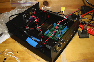
In the meantime, I've been working on the case and power supply. I purchased the HobbyCNC EZ Driver package which included everything needed except a 24V 10A transformer and case. A PacTec DM-4 case was recommended along with a couple of transformers. The transformers were out of stock. A friend gave me an industrial 24V 12A transformer mounted in a NEMA 1 case. It's much too big to fit inside the PacTec case so I'll be mounting it externally and deviating from the plans.
The plans call for a wiring path something like this:
- AC 110 from the wall
- Power switch
- Hot wire through 4A fuse
- Transformer
- Bridge rectifier
- Capacitor
- Negative wire through 10A fuse
- Driver board
I'll be going:
- AC 110 from wall
- Hot wire through 6A fuse (to be reduced to 4A)
- Transformer
- AC switch
- Bridge Rectifier
- Capacitor
- Negative wire through 10A fuse
- Driver board
So I've left out the 4A fuse in the case and the switch is on the 24V AC lines. Not being an expert in electricity, I had to run this by my dad to make sure the rating on the switch was good for this. It's marked AC 125V 10A so I should be fine. Apparently it's a big No-No to switch the DC lines as some fantastic thing happens in the motors and the driver blows up. I hope I don't blow the fuse...
I tested things as I went. The transformer secondaries produced 24V AC as expected. I temporarily connected them to the bridge rectifier but couldn't get a stable reading of DC output. This is because the AC/DC conversion produces a "wave" of current or voltage or whatever. After connecting the capacitor, things smoothed out and I got 32V DC output. I was expecting the output to be greater than 24V but I haven't had time to look up the theory that explains this.
Here's the transformer with wiring exposed with a 9V battery for scale (I didn't have a quarter handy). I studied it a bit to find out it was properly wired.
Here's the case prior to work.
Here's the case with all the parts in place. I haven't committed to anything yet. The capacitor and the driver board are just sitting in place. I haven't even put the heat to the heat-shrink tubing yet. I'd like to see some motors move first. I tested the DC output and I'm getting 32V. I applied this to the driver board and got 5V logic on the test pad. So far so good. Next is to solder on the driver chips and install the heat sink. I'll be using my mill for the heat sink, so I'll need good dimensions first for the screw holes.
Here's a shot of the front of the case. The plans called for 10 5/8" holes for ventilation. But I've got a mill and a DRO - I'm not afraid to use it! So I made 40 slots. That looks better.
And the transformer nicely wired and ready to go.


Hi Daryl
ReplyDeleteIt's interesting that your first sub-project is to build the electronics case (with PSU), which will probably be the last thing I will do. You case is nice and you're setting a high standard for me to match...
32V DC from 24V AC: Looks to me like this is sqrt(2) x 24, ie, you might be reading the peak AC voltage as the DC voltage ? Have you tried to read the DC voltage when the system is under (reasonable) load ?
"Apparently it's a big No-No to switch the DC lines": Yes, don't do it (or do it and let me know what happens :-) ). Basically the driver wants to 'ease out' residual current through the power supply when it shuts down. It's also a consideration when attaching an emergency stop switch. It probably should live on the AC side.
Re Lost Post: Sorry to hear that. A faint chance may be to hit the BACK key a number of times and hope your browser cached it and brings it back to you.
Thanks Thomas. I actually worked on the software first. I needed to be sure that if I had to write the entire software stack I could do it, and I'm pretty sure I can. I bought this kit because I don't know how to design such a controller. I needed to apply 12-36V to the driver board to test it and I didn't have any such source, so I just built the power supply in the kit!
ReplyDeleteRegarding E-stop on the AC side, it takes like 10 minutes to drain the filter capacitor, so I don't understand how an AC E-stop could work. My plan is to do E-stop with the Arduino and just stop sending step signals.
I dug pretty deep in the browser cache (Chrome) and couldn't extract anything useful.
Thanks for the reading and commenting.